UV curing hot-plate
Tool which will help me with making PCBs
07.11.2025
Purpose
The way I make PCBs requires applying PCB resin. Curing the resin only under UV light is very slow, but if I heat it up, the curing time becomes much shorter.
Build logic
Before building this, I did the process on a hot plate (fairly big, but not as big as this), and after some time I moved it under the UV lamp, which had some very sketchy 3D-modeled legs and a fan holder above it.
This setup could work, of course, but it’s not great if you want to make PCBs often.
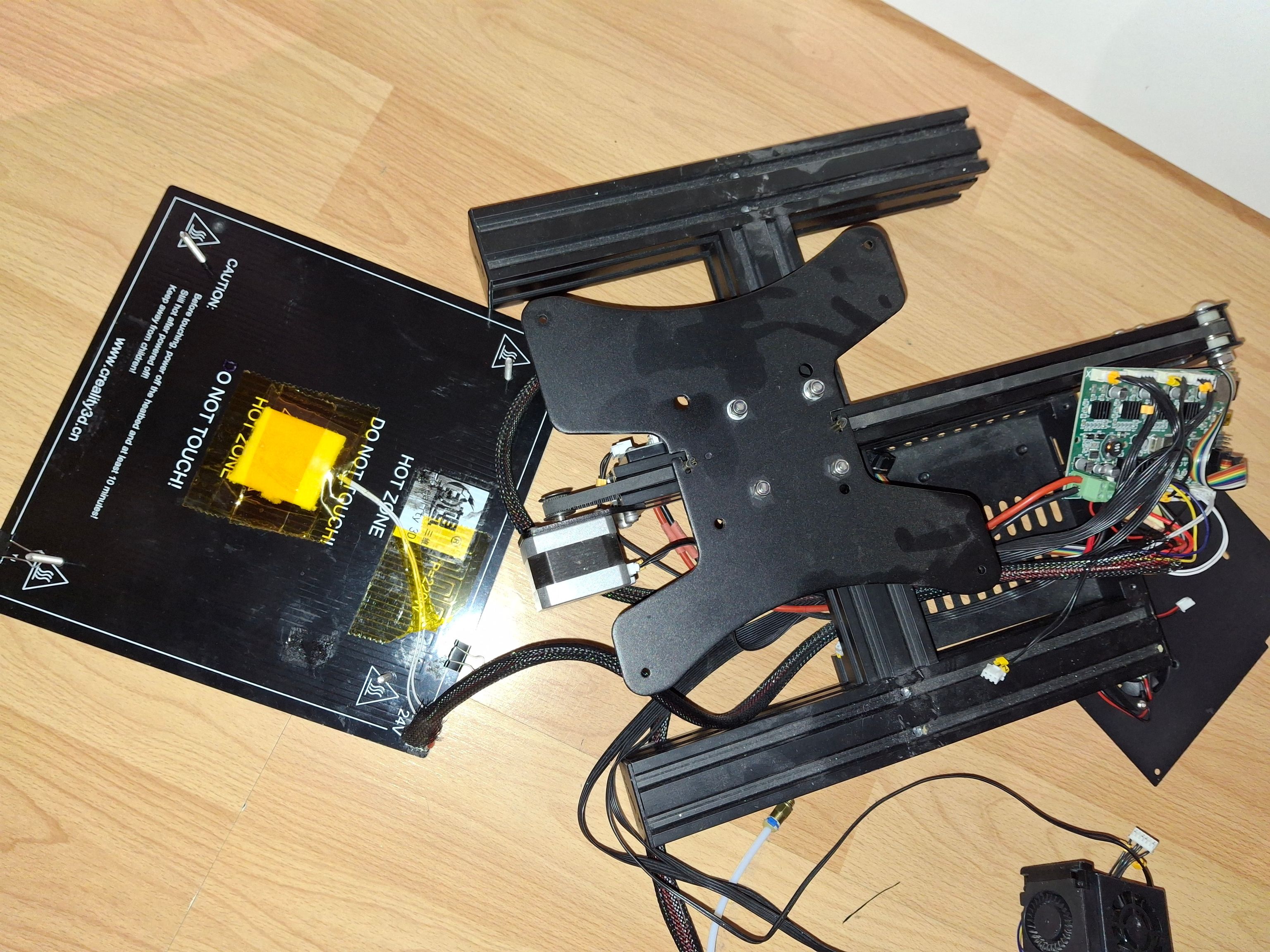
I got the idea to build this while doing the process. I was looking around and had a “heureka” moment when I saw my Ender 3 printer bed lying around. I realized I could use its bed instead of the hot plate.
Hardware
I also decided to use the Ender’s motherboard, because:
- it already has all the hardware I need (bed heating circuitry, display and thermistor connectors, etc.)
- it currently has no other purpose
Firmware
At first I wanted to customize my own Marlin config, because it already has everything needed to control the hardware. That didn’t work out, because it wasn’t as straightforward as I expected. I would’ve had to read through all the Ender 3 configs and actually understand how everything works, so in the end I decided it wasn’t practical.
The next option was to build it all myself.
Even though the most popular choice would be Arduino IDE, I didn’t want to use it again. In the recent past I used the plain AVR compiler, and that opened my eyes to how MCUs actually work.
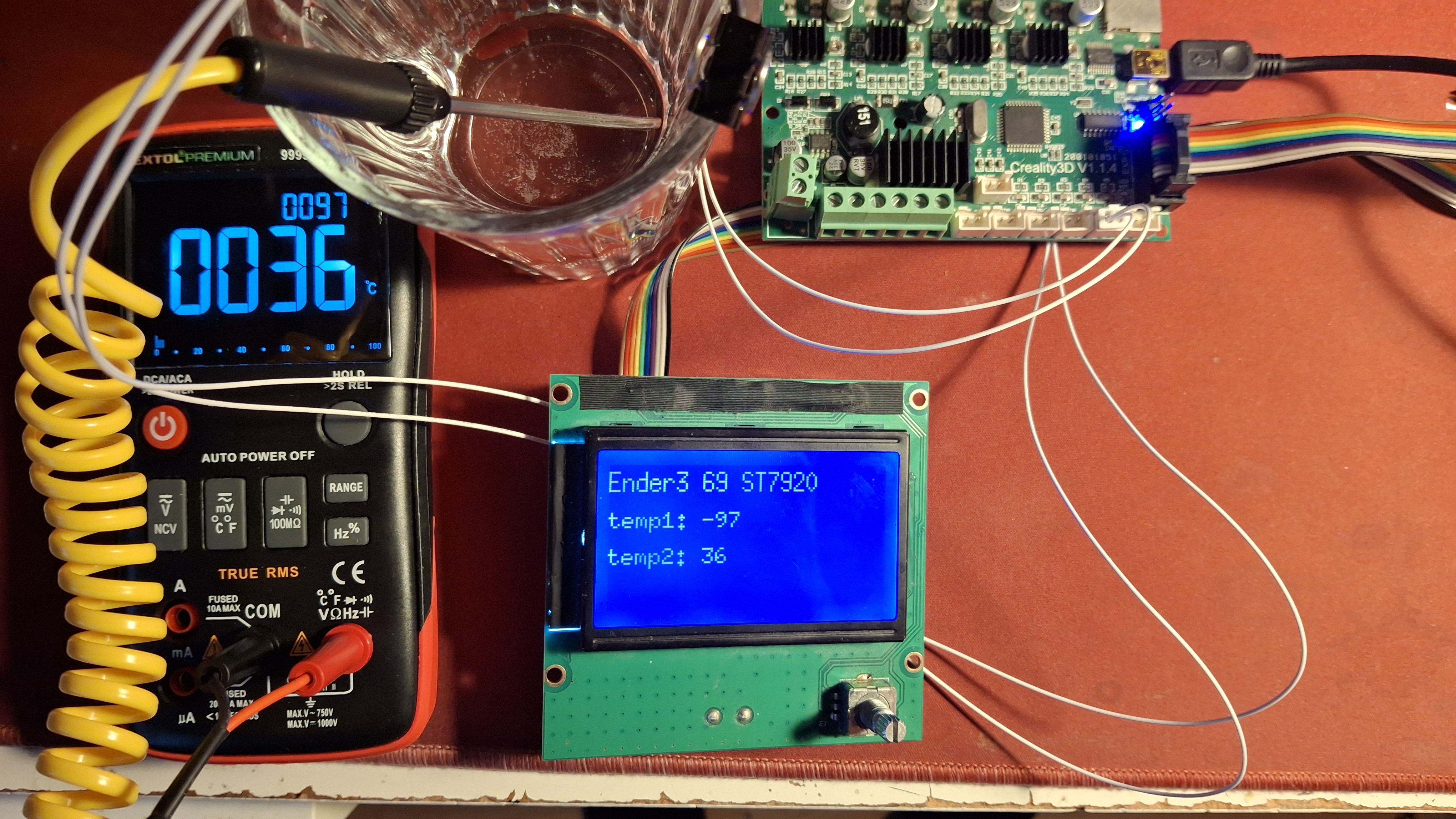
Luckily, I discovered the display has an AVR-compatible library, which saved me some time. After that it was just incorporating every sensor and putting everything together.
The Build
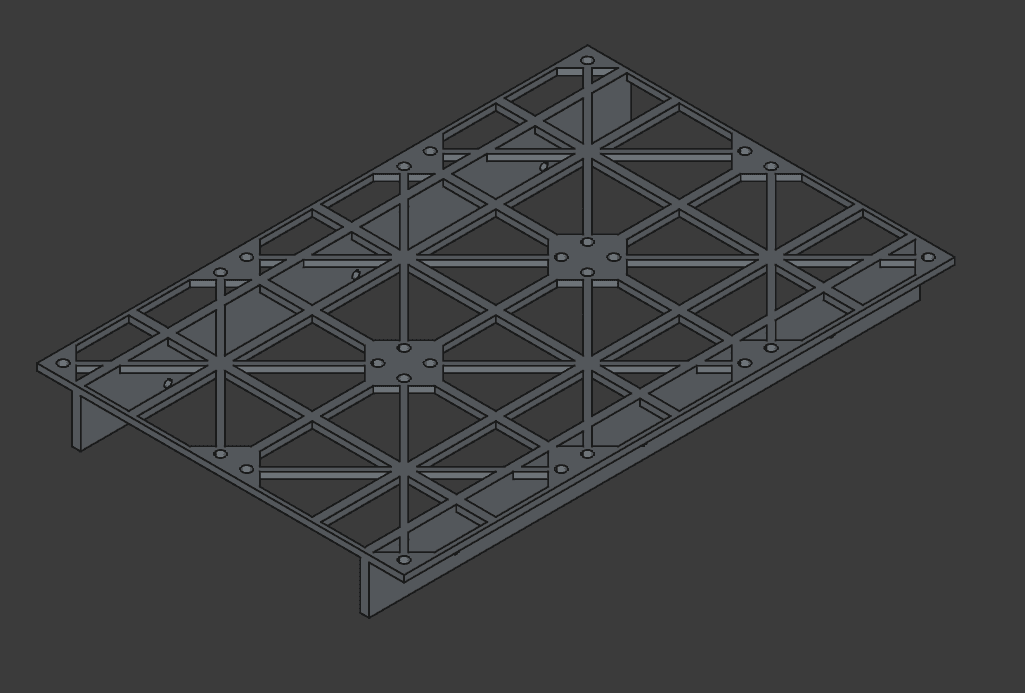
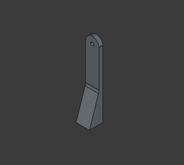
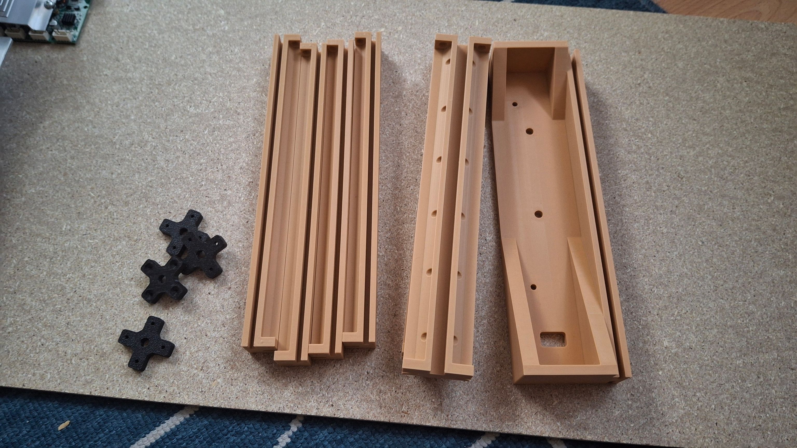
The main materials were wooden boards and 3D-printed wall adapters.
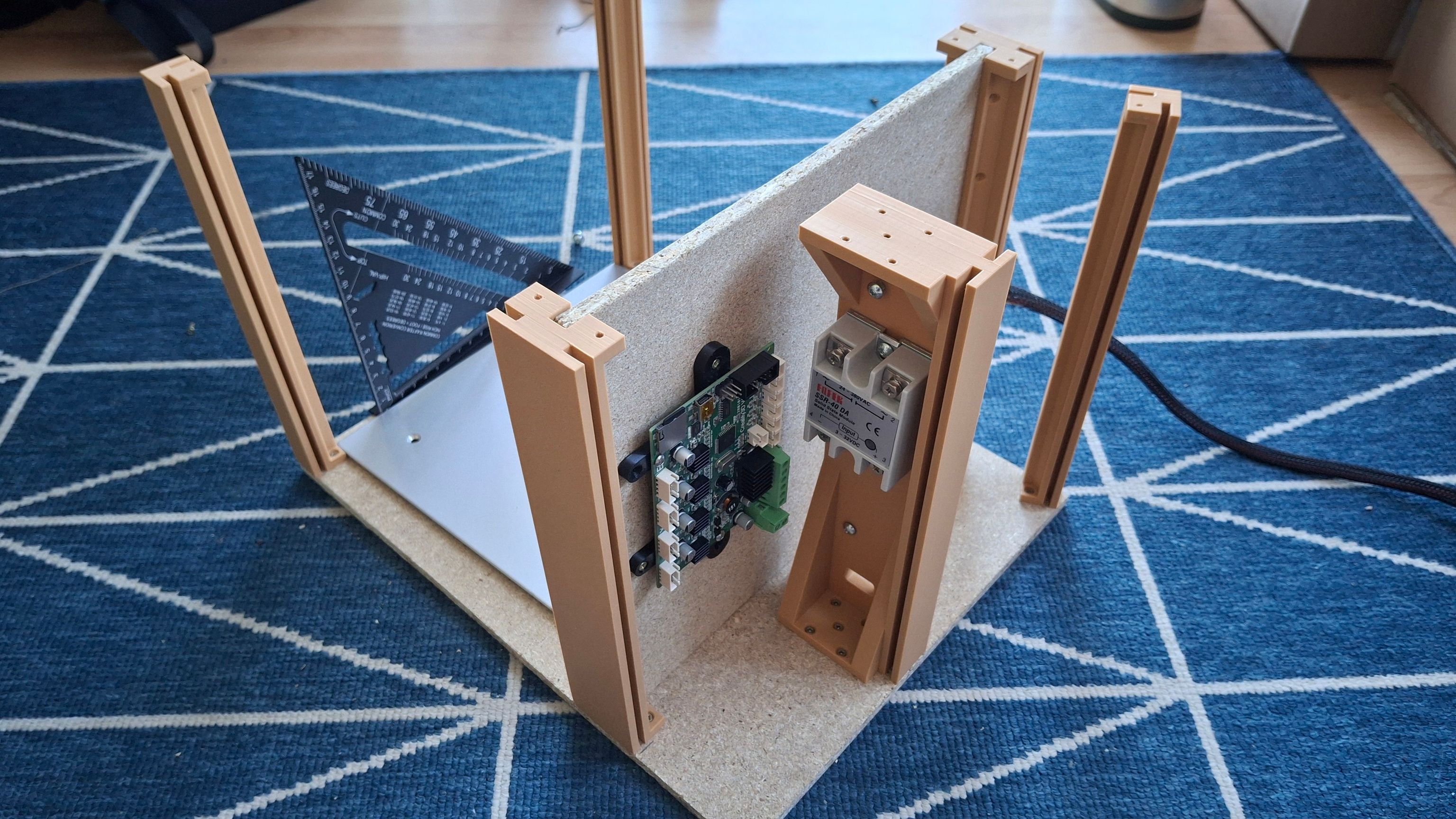
The design was fairly simple. I was mainly constrained by the (big) power supply and the bed. With the wooden board I had, this is the layout I liked the most: the bed is in front (how else…), the power supply is in the back standing vertically, and between them there’s a wall where the MCU and the solid-state relay are mounted.
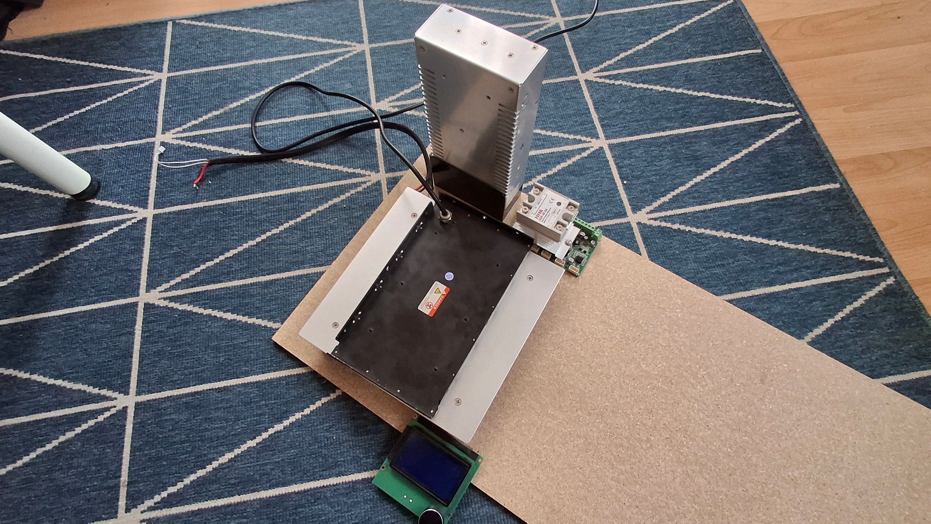
This was the components spread on the board so I could imagine the setup.
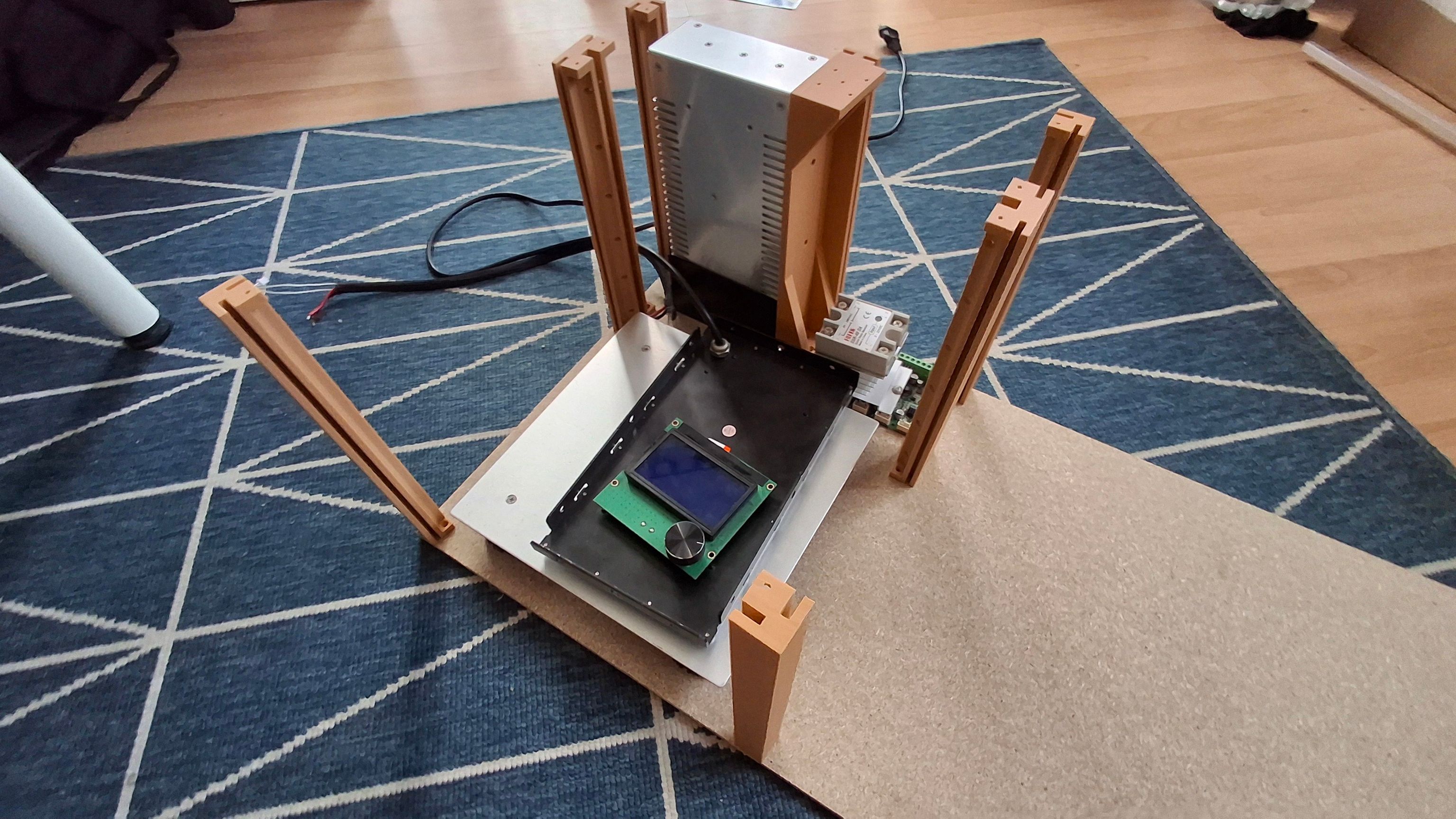
After some time in CAD (and even more time 3D printing), I had the pieces in the right places and it was looking promising.
Finally, I bought a table saw (because with my limited space I couldn’t fit a big one anywhere), so I wouldn’t have to do it with a regular handheld saw. But because the table saw is small, it was kinda sketchy. To even fit the big chunk of wood on it, I had to remove the rollers for the sandpaper. Cutting the wood was also kinda bad, because most of it was hanging in the air and I didn’t have a proper rail to feed the wood in a straight line.
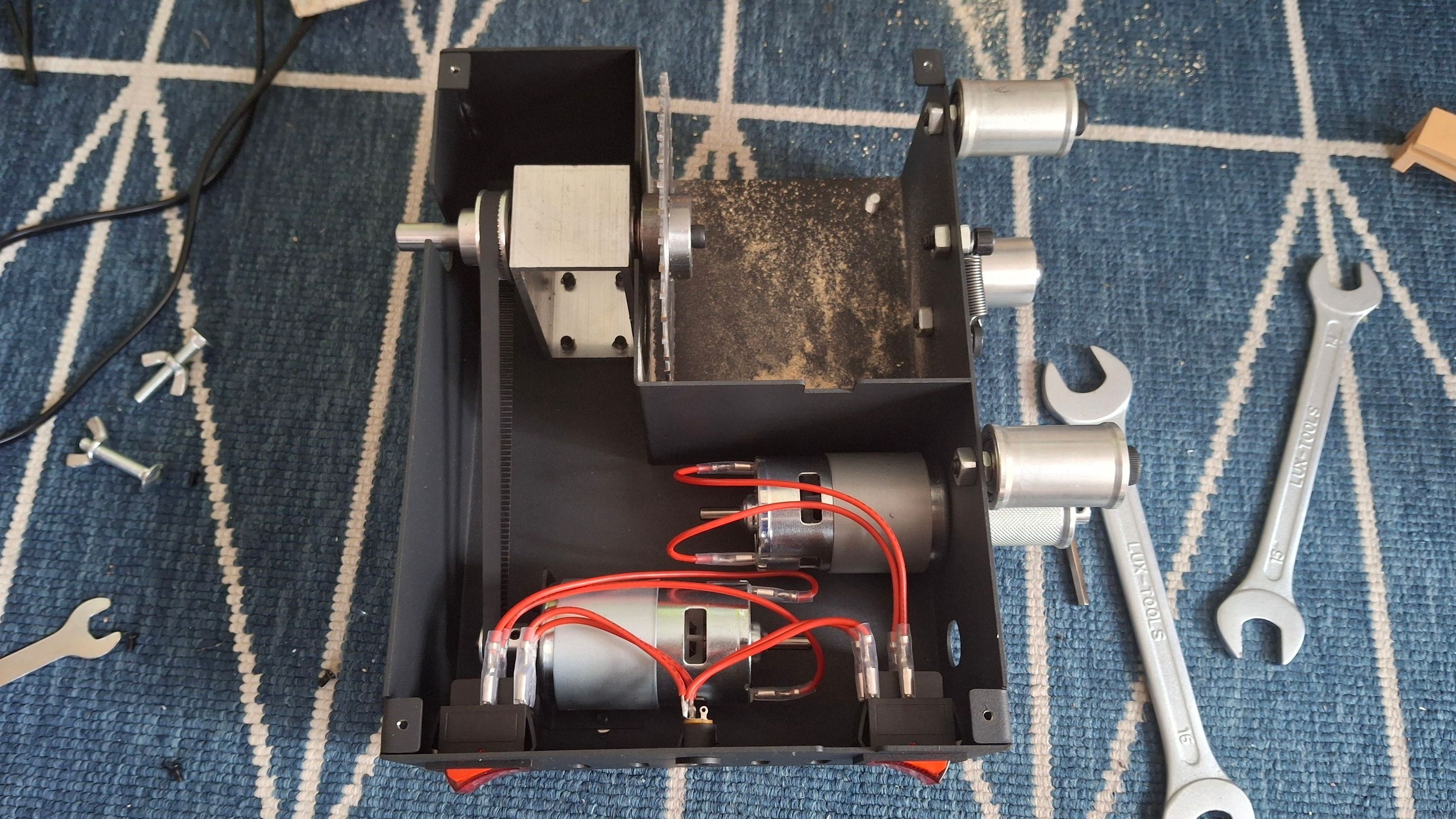
Table disassembled
Now that I’m writing this and thinking about how sketchy that was, I could easily extend the saw’s table and make it removable, so space wouldn’t be a problem.
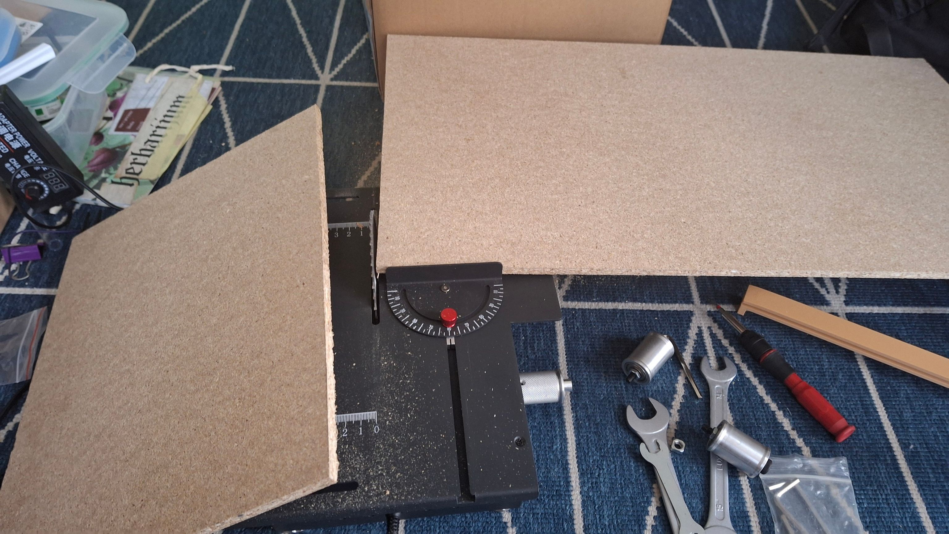
Board cutting
Assembly
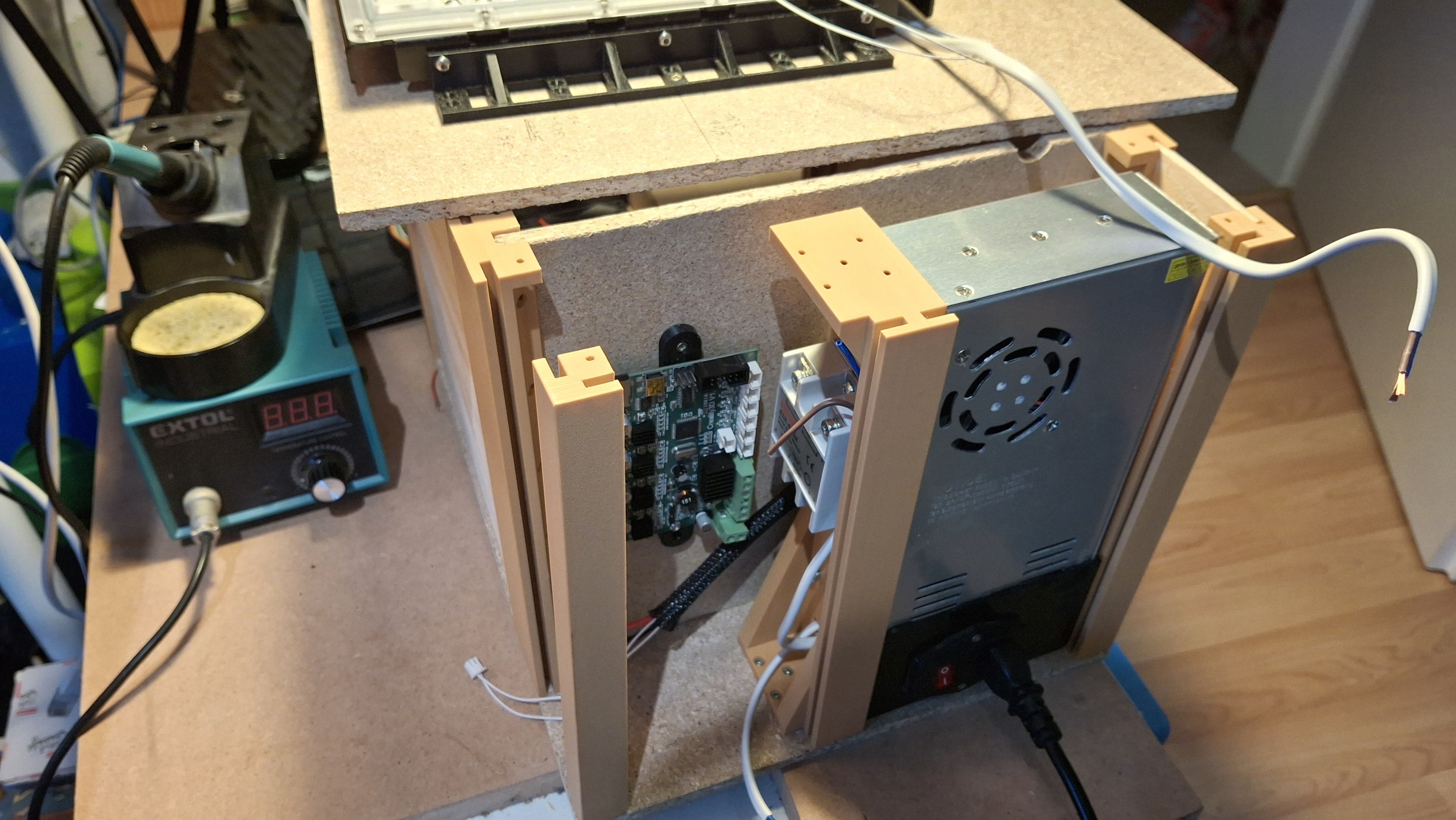
Assembly was straightforward. Screws had to be used to hold the printed parts in place.
screwed
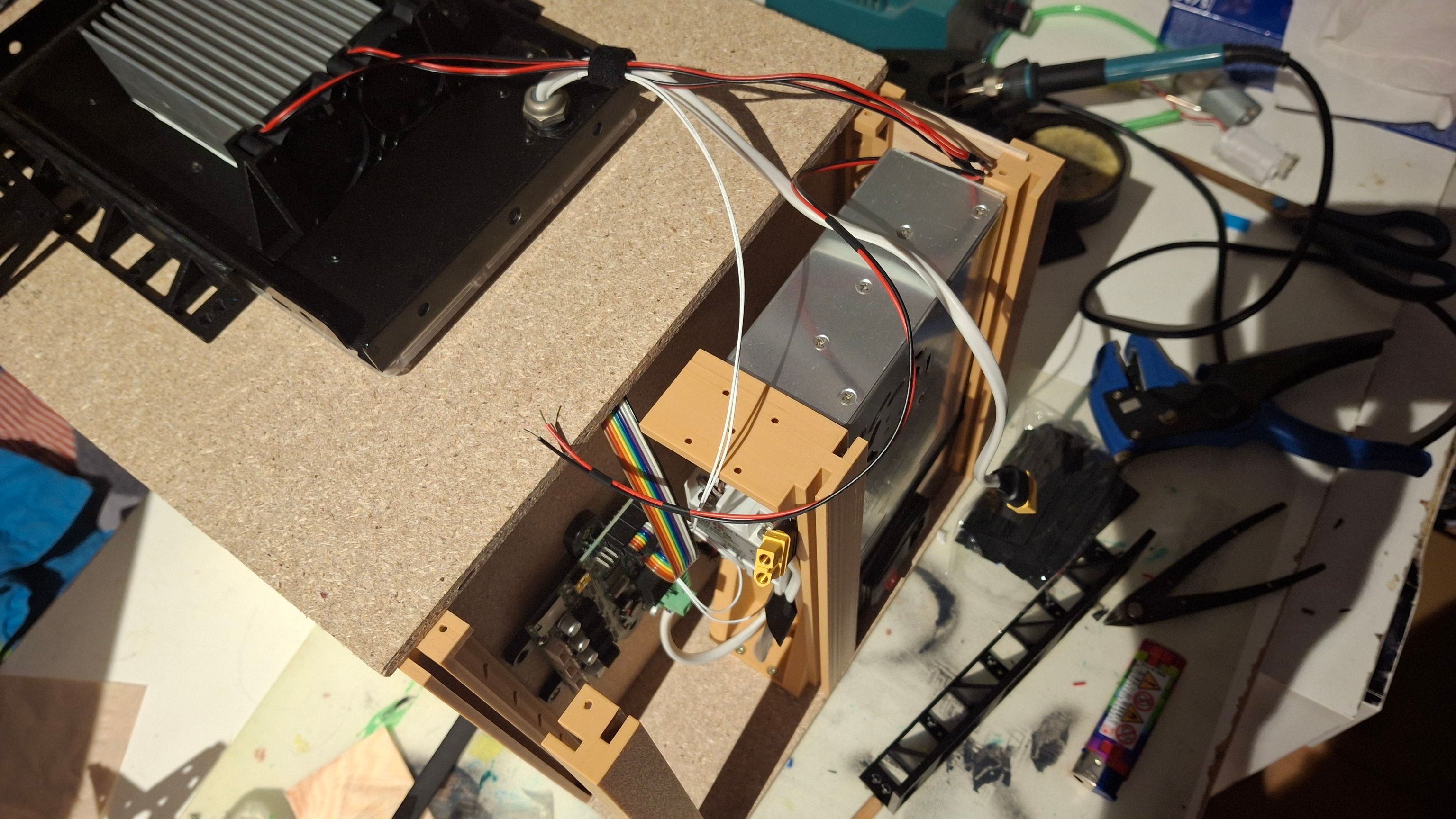
After everything was in place, I had to wire everything.
screwed
One unfortunate thing is that I didn’t care about the top cover, so I didn’t add any way to secure it. In the end, I had to drill each printed pillar to add threaded inserts.
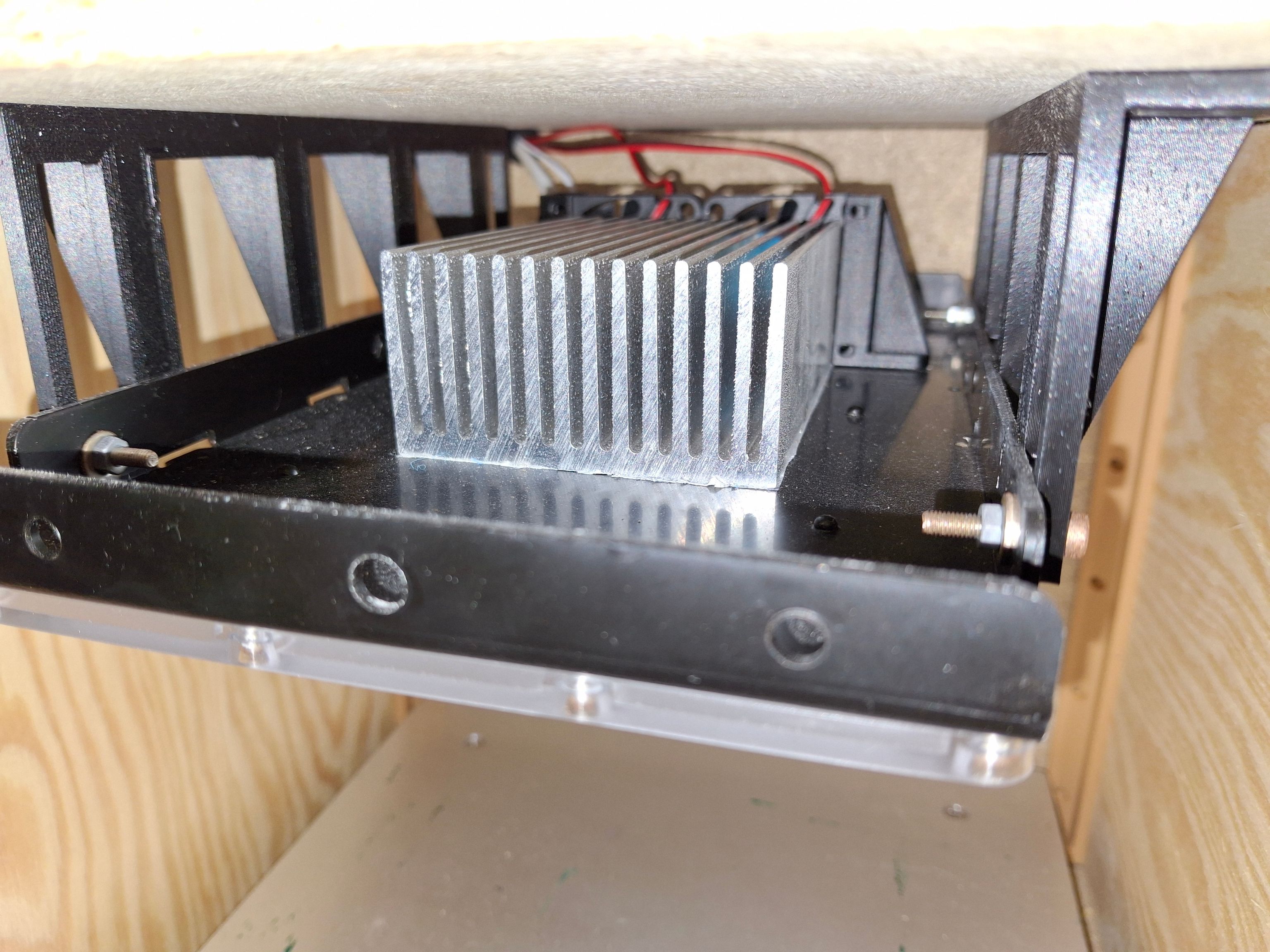
Fans
After some usage (thanks to the programmed temperature limits), I noticed the UV lamp was getting hotter than I’d like.
I fixed it by securing a large heatsink to the UV lamp and adding small fans to the back side. The fans were wired to the Ender PCB on the fan terminal. Unfortunately, that terminal is wired directly to 12V, so I can’t control it.
This fixed the issue, and now it can run indefinitely without overheating.
Testing
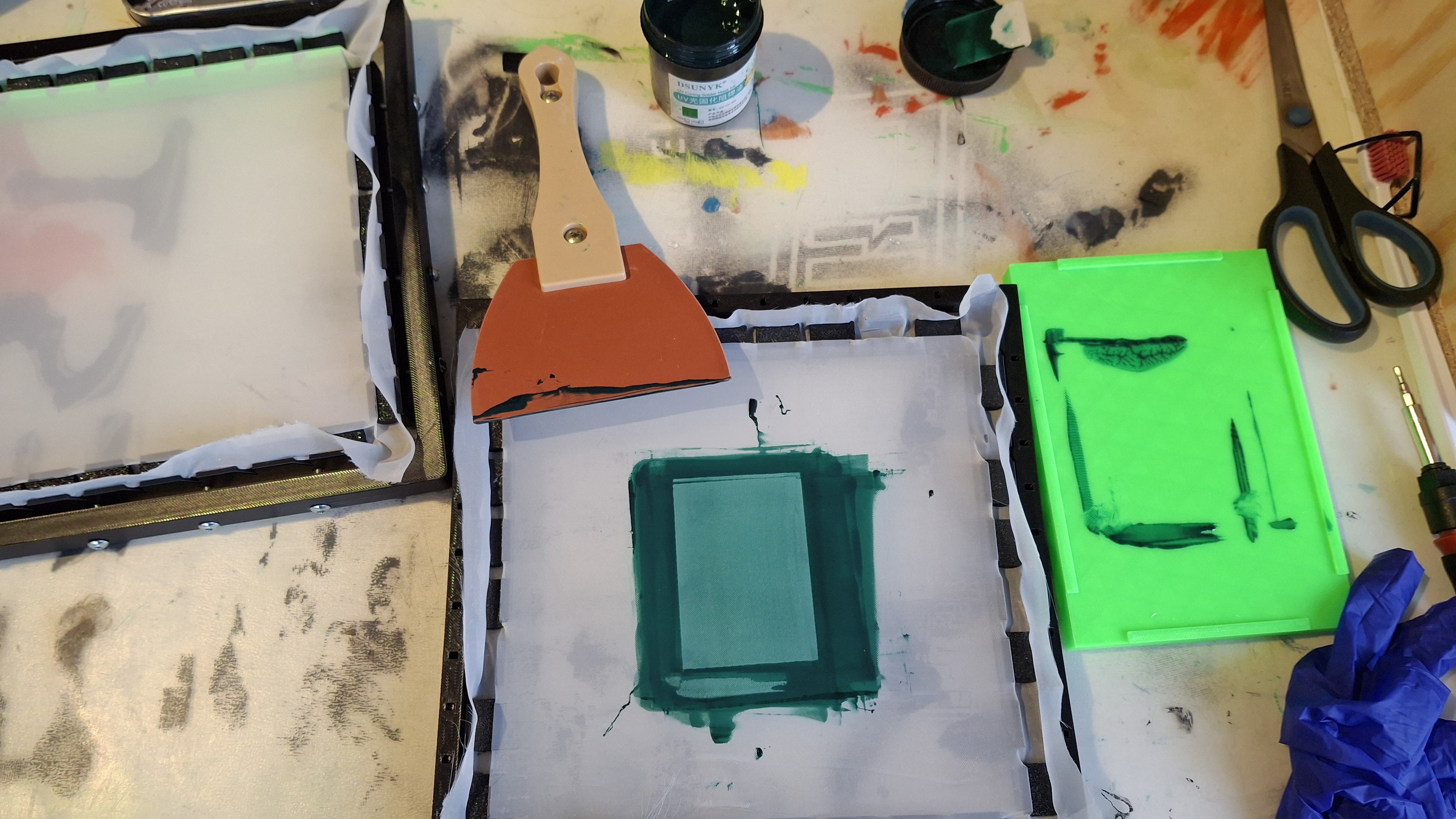
Applying the UV resin layer:
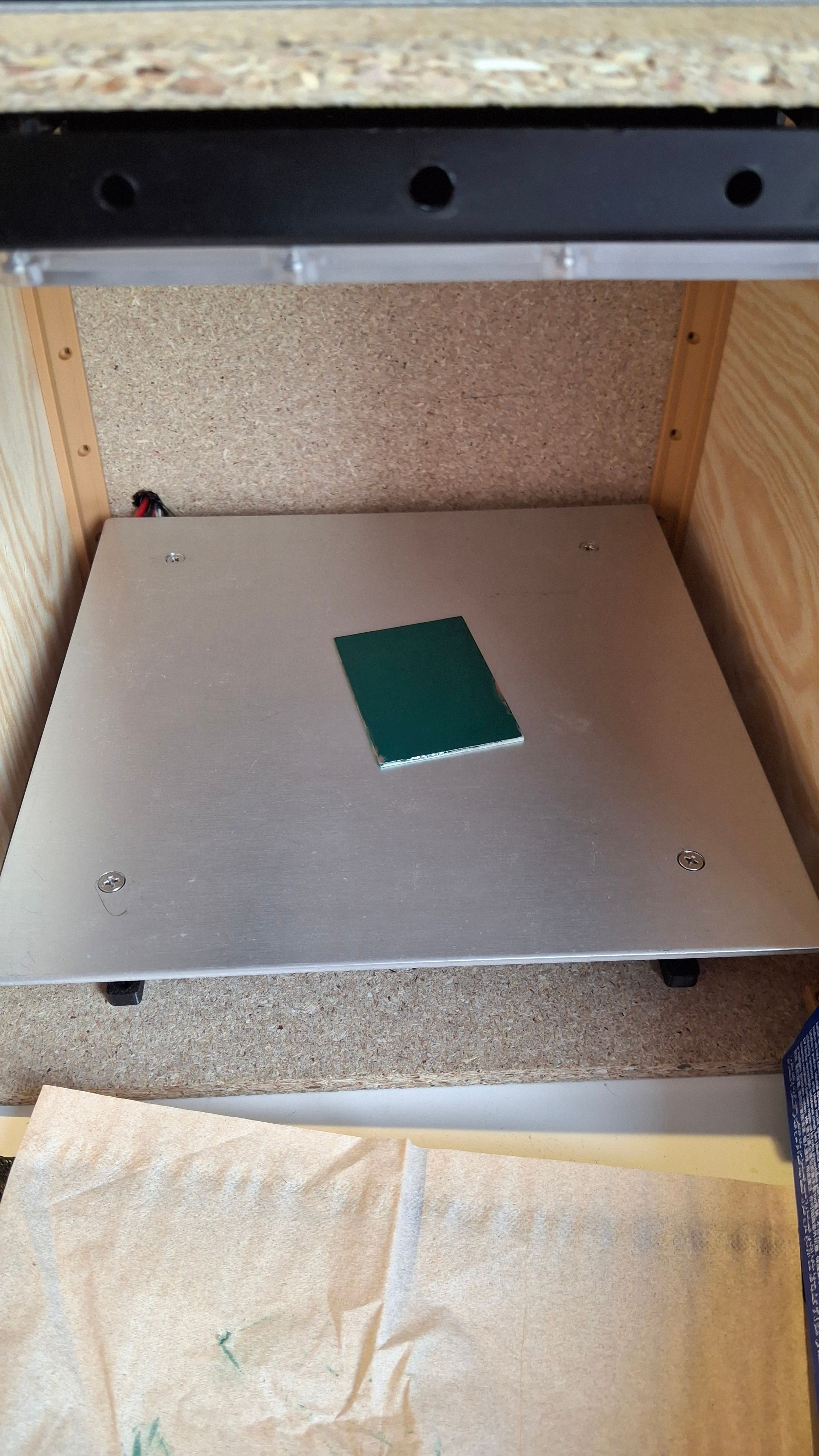
Settings which work for the first resin layer:
Temp: 80 deg
Time: 15 min
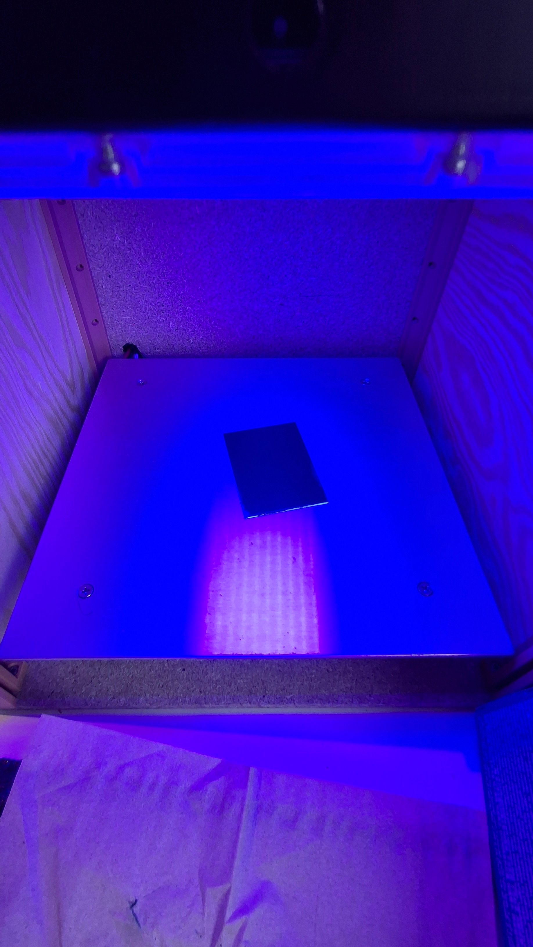
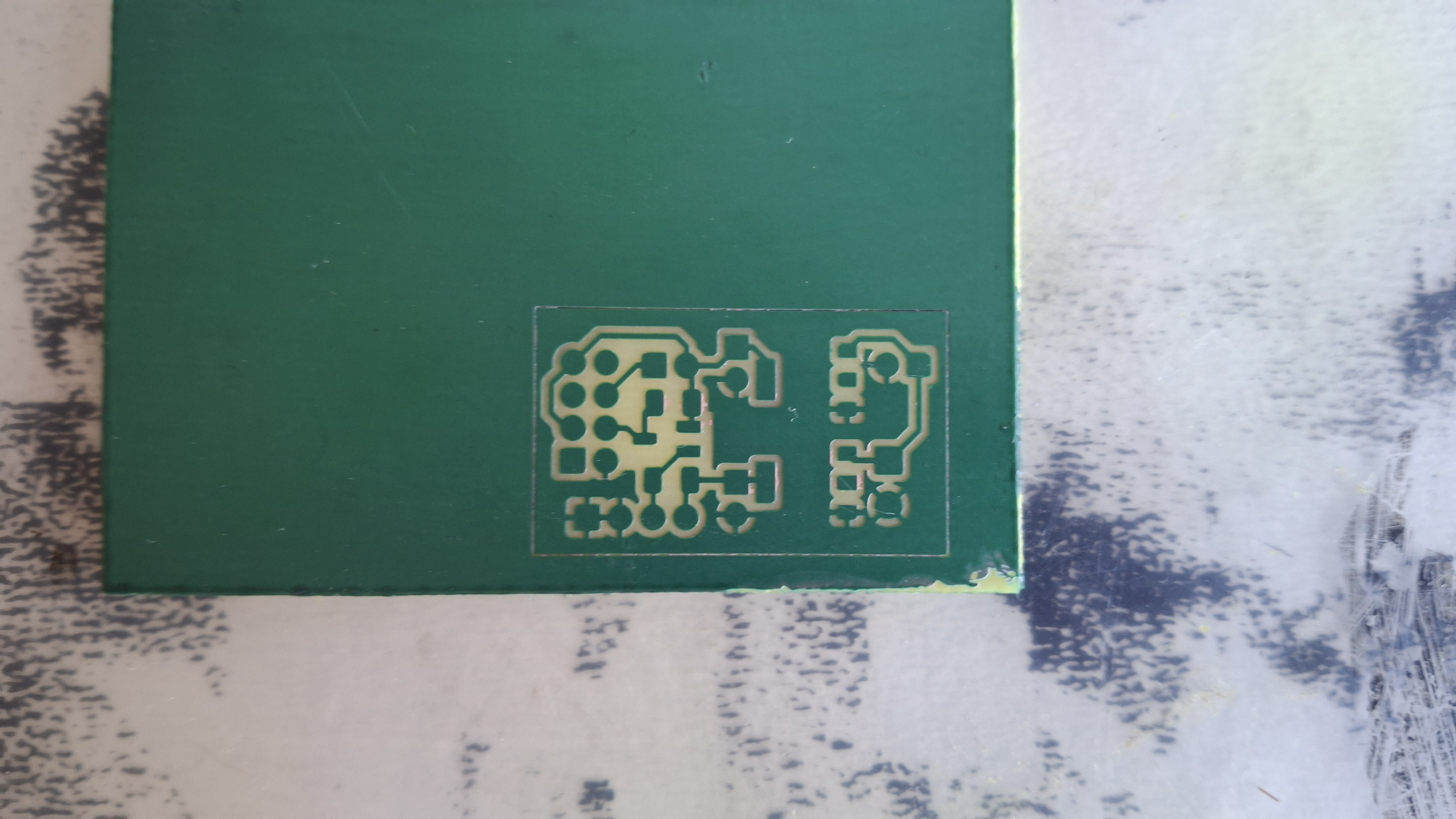 And after some “magic”
Conclusion
This project ended up better than I expected.
But there’s still room for improvement:
- UI is very unresponsive
- can’t control the UV lamp’s fan
- still nowhere to secure the display
Plans
I’ll see how much I end up using it. I’d like to create a custom PCB for the control, use an ESP so I can have the control panel in a browser, and add proper fan control.