Gowin IDE Tutorial: Blink an LED on Sipeed FPGA Boards
Learn how to use Gowin IDE to create, synthesize and program a blinking LED project on Sipeed FPGA boards using Verilog.
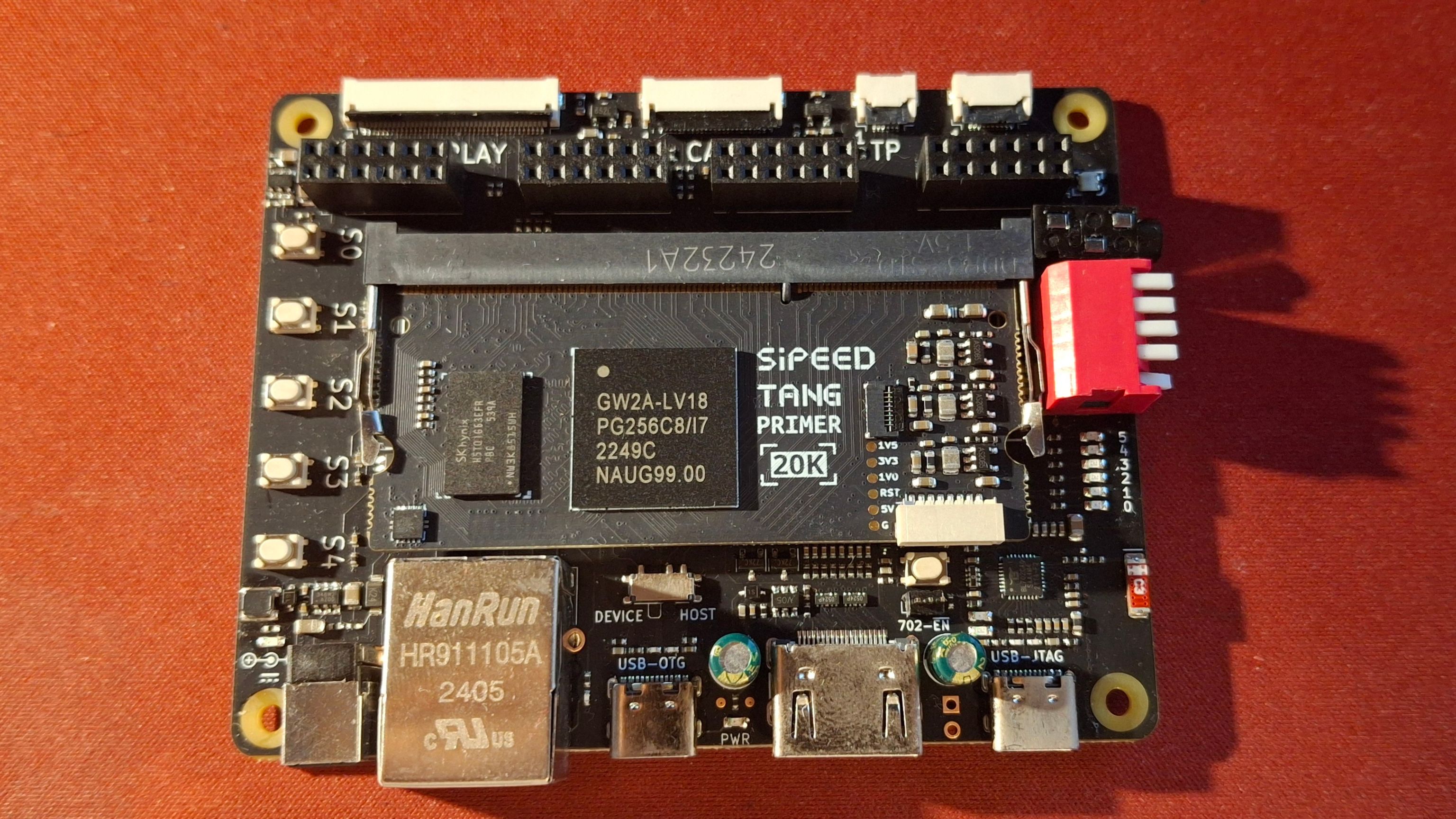
Sipeed Tang Primer 20K Dock
Unfortunately, while getting started, I could not easily find a text tutorial showing the whole process from creating a project to seeing the LED blink. That is why I am making this tutorial.
In this tutorial I will show you how to create and configure a project, write a basic Verilog file, synthesize it, configure the pins, run place and route, and finally program the board and enjoy the blinking LED.
I am using the Tang Primer 20K in the screenshots, but the same process also works for other Sipeed boards using Gowin FPGAs. You only need to select the correct FPGA device and use the correct LED and clock pins for your board.
Creating the project
The first step is to launch Gowin IDE. I am using the free Education version V1.9.11.03.
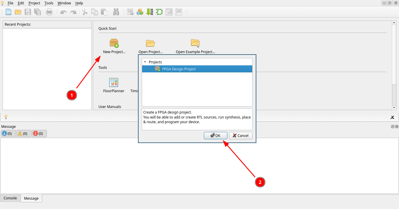
Click on New Project... and confirm you want to create an FPGA Design Project.
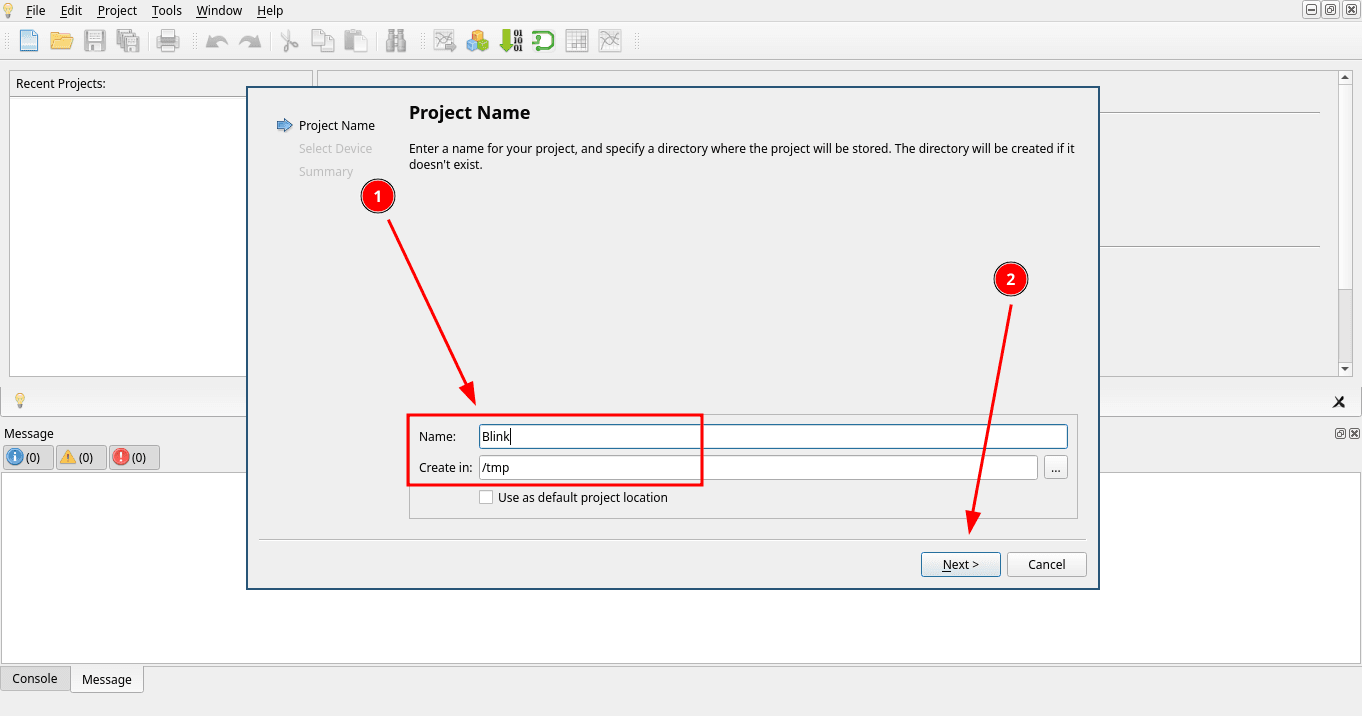
Give the project a name. I called mine Blink. Then pick a directory where it should be created.
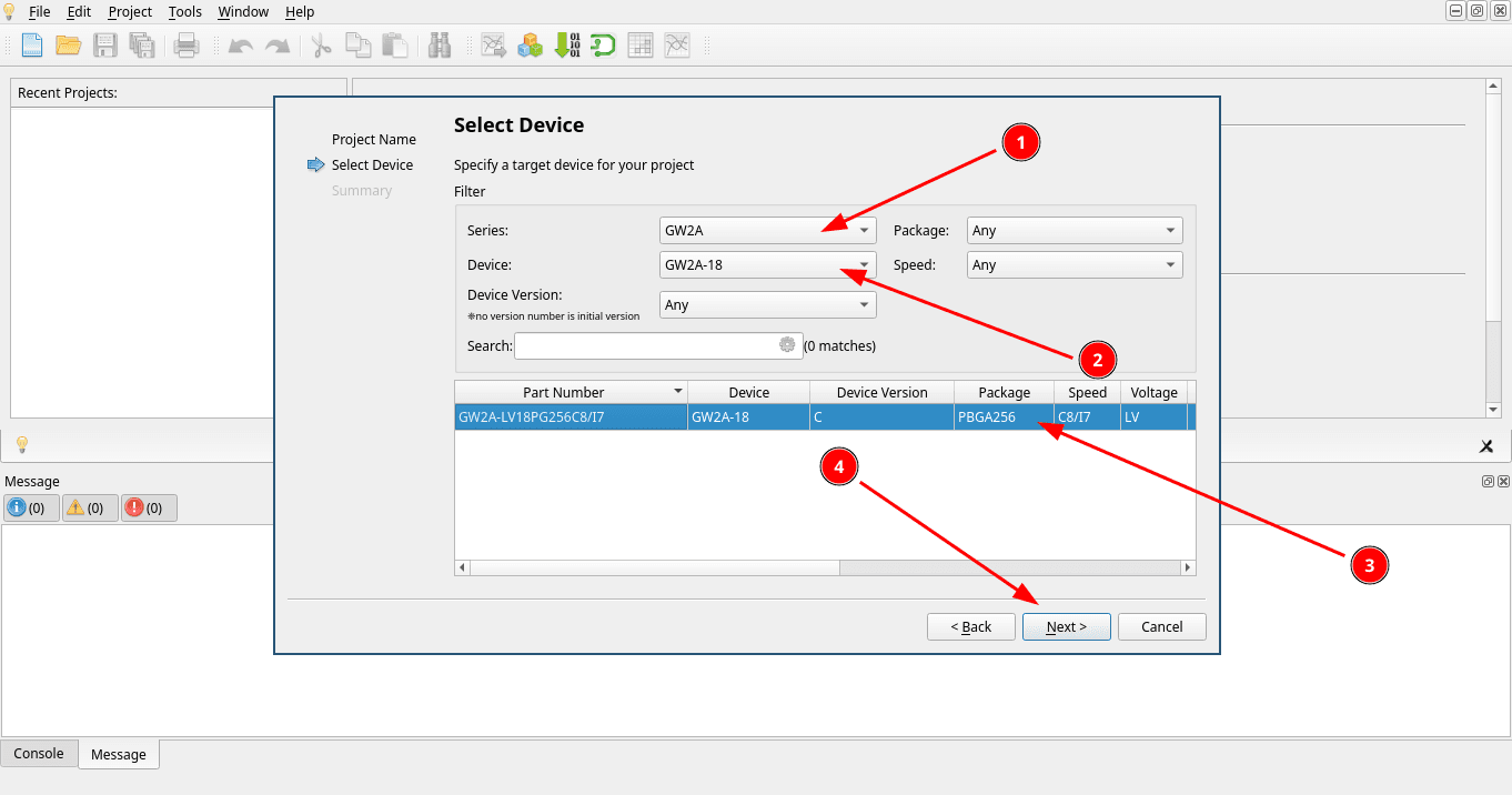
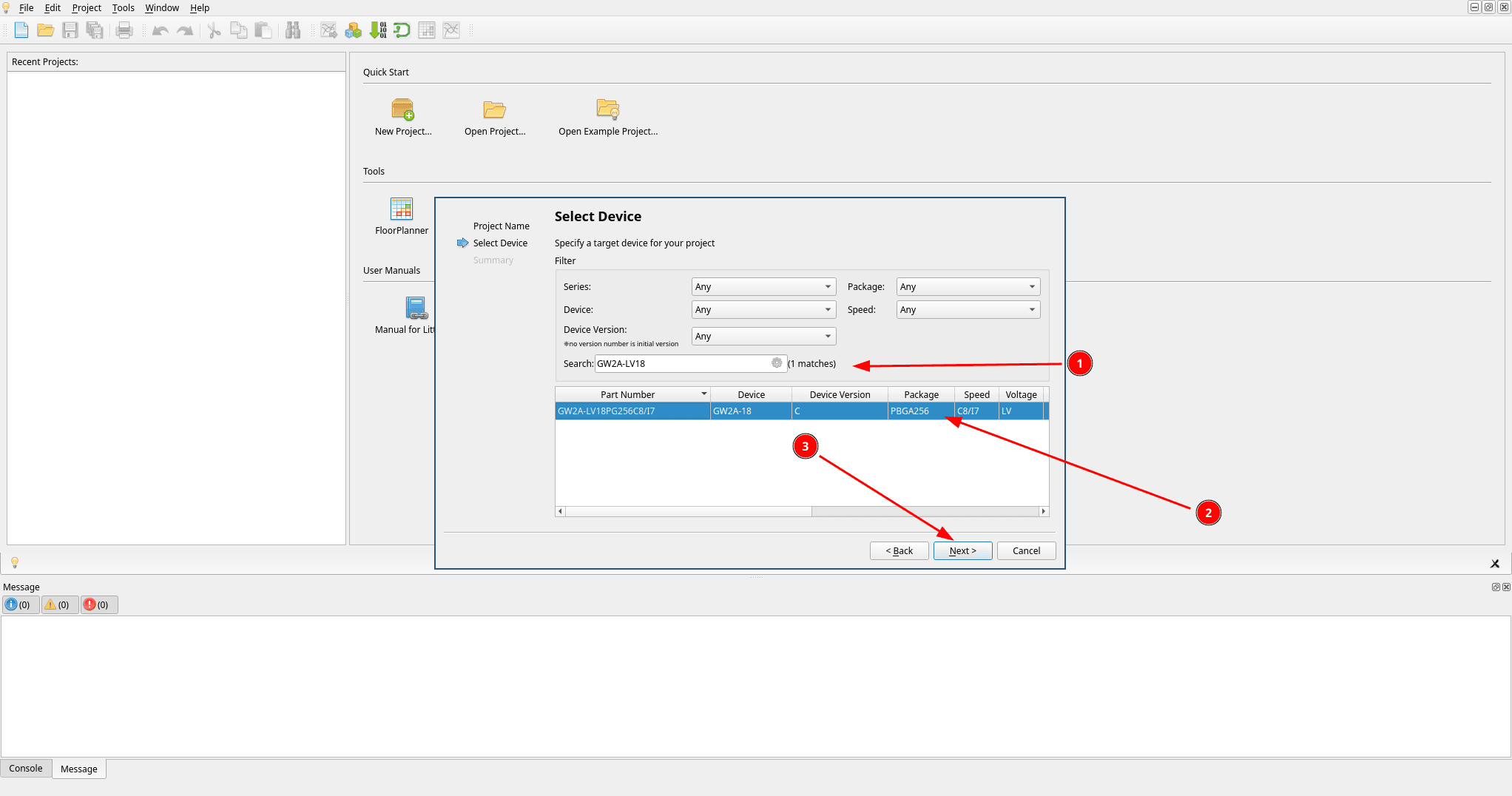
Now select the device you are targeting. You can filter it using the Series and Device dropdowns. If you already know the exact part number, it is much faster to type it directly into the Search box. Mine is a GW2A-LV18PG256C8/I7.
Make sure you select the FPGA device used by your board. The device shown in the screenshots is for the Tang Primer 20K.
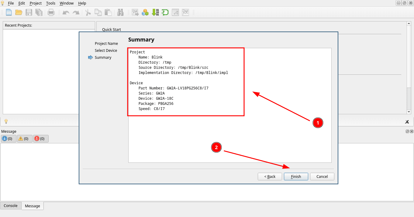
The last step of the wizard is a summary of everything selected so far. Check it and click Finish.
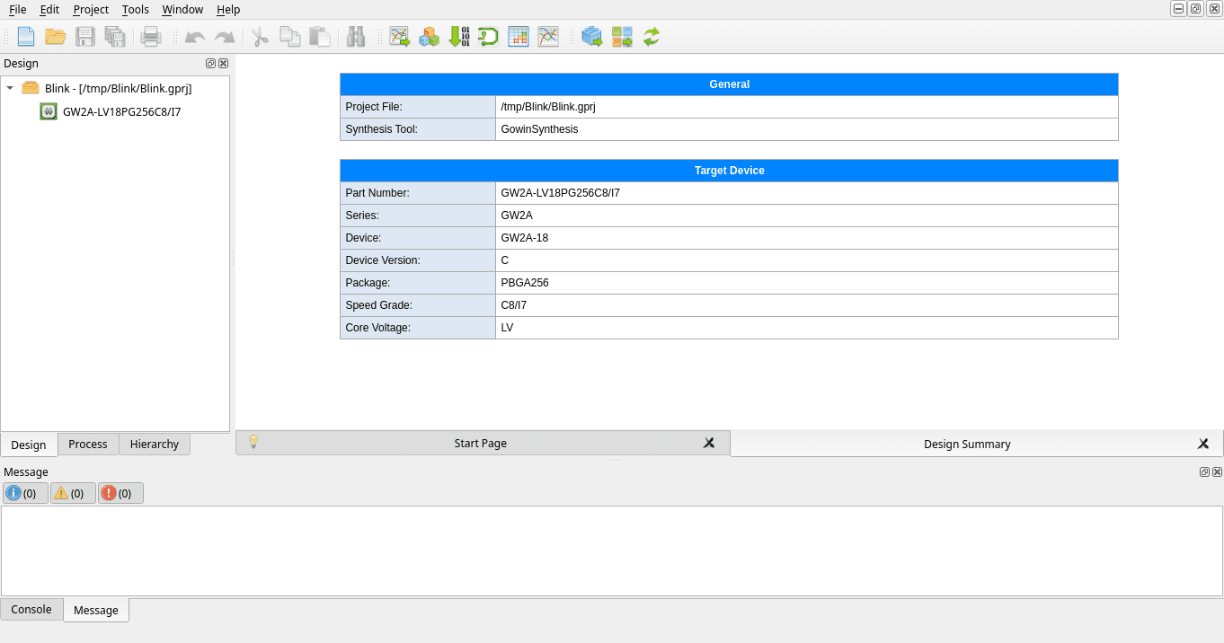
The project is now created and opened, showing the Design Summary with the project file, synthesis tool and target device.
Writing the Verilog
Time to write some code, so create a new Verilog File.
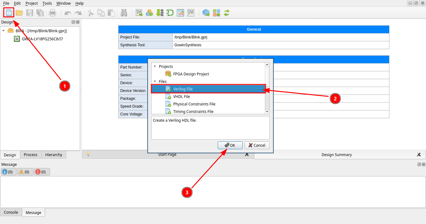
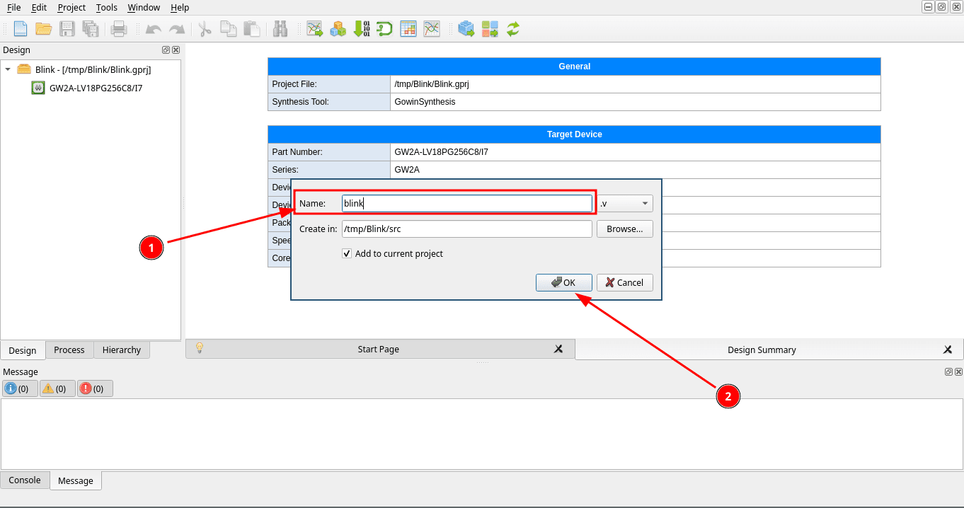
Name it blink. The .v extension is added for you. Leave it in the project’s src folder.
Now paste the following code into the file and save it. The code is explained below.
module blinkLed(
    input wire clock,
    output wire led
);

    reg [24:0] counter = 25'd0;

    always @(posedge clock) begin
        counter <= counter + 1'b1;
    end

    assign led = counter[24];
endmodule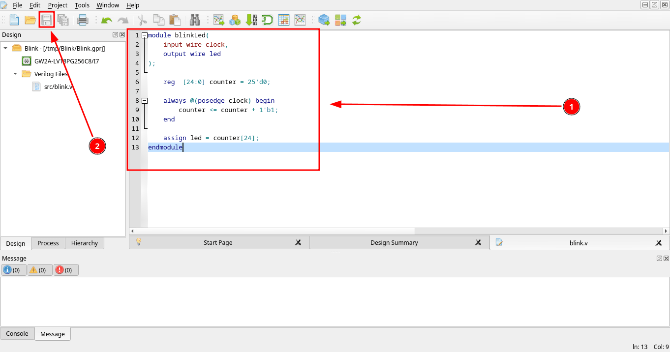
How the Verilog code works
module blinkLed(
    input wire clock,
    output wire led
);

endmodule
This is the definition of the blinkLed module, which has two ports. clock is the incoming clock signal and led will be connected to the LED pin.
reg [24:0] counter = 25'd0;Inside the module there is a 25 bit register called counter. This is our variable for storing the current clock count. It starts at 0.
always @(posedge clock) begin
    counter <= counter + 1'b1;
end
This is the part of the code that increases the counter by one every time the clock changes from low to high.
assign led = counter[24];The LED is connected to counter[24], which is the highest bit of the counter. This bit changes much slower than the input clock, making the LED blink at a speed that we can see.
The Tang Primer 20K has a 27 MHz clock, so we can calculate how long it takes for counter[24] to change:
2^24 / 27_000_000 = 0.621sThis is how long it takes for the LED to change from on to off or from off to on. A full blink cycle therefore takes about:
2 * 0.621s = 1.243sSynthesis
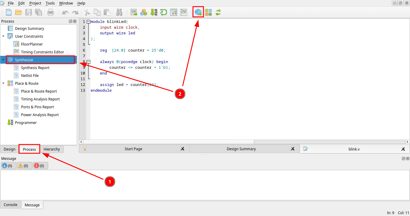
With the code saved, double click Synthesize in the Process panel to run it. You can also click the Synthesis icon in the top toolbar.
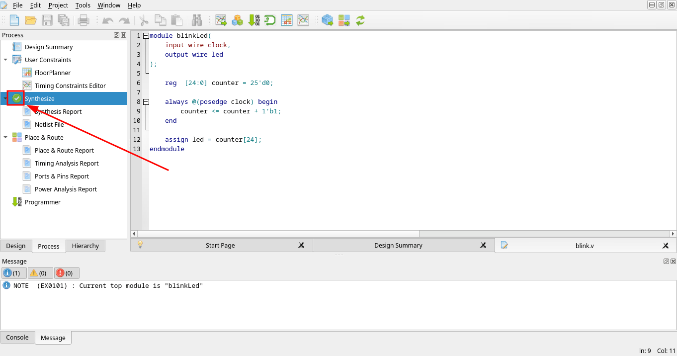
If everything went fine, you should get a green checkmark and a note confirming that blinkLed was selected as the top module.
Pin assignment
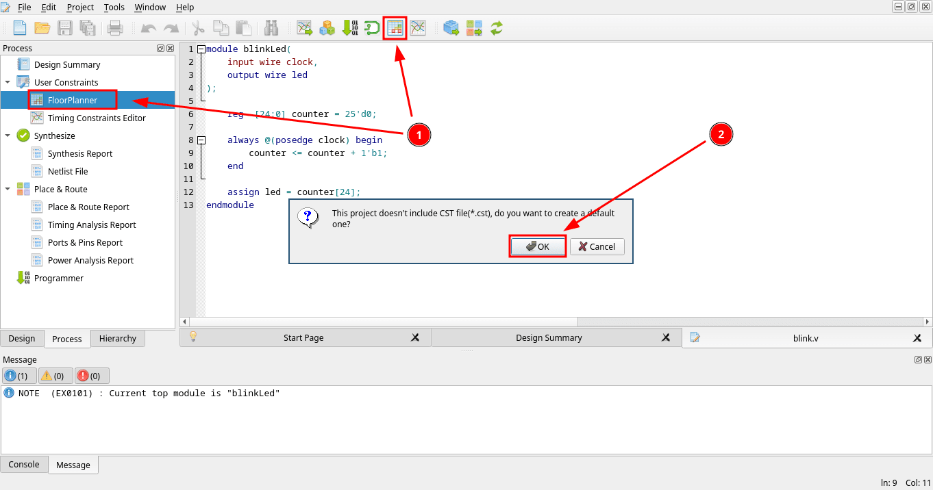
Next, open FloorPlanner from the Process panel or the top toolbar to assign the pins. Since this project does not have a constraints file yet, it will offer to create a default one. Confirm with OK.
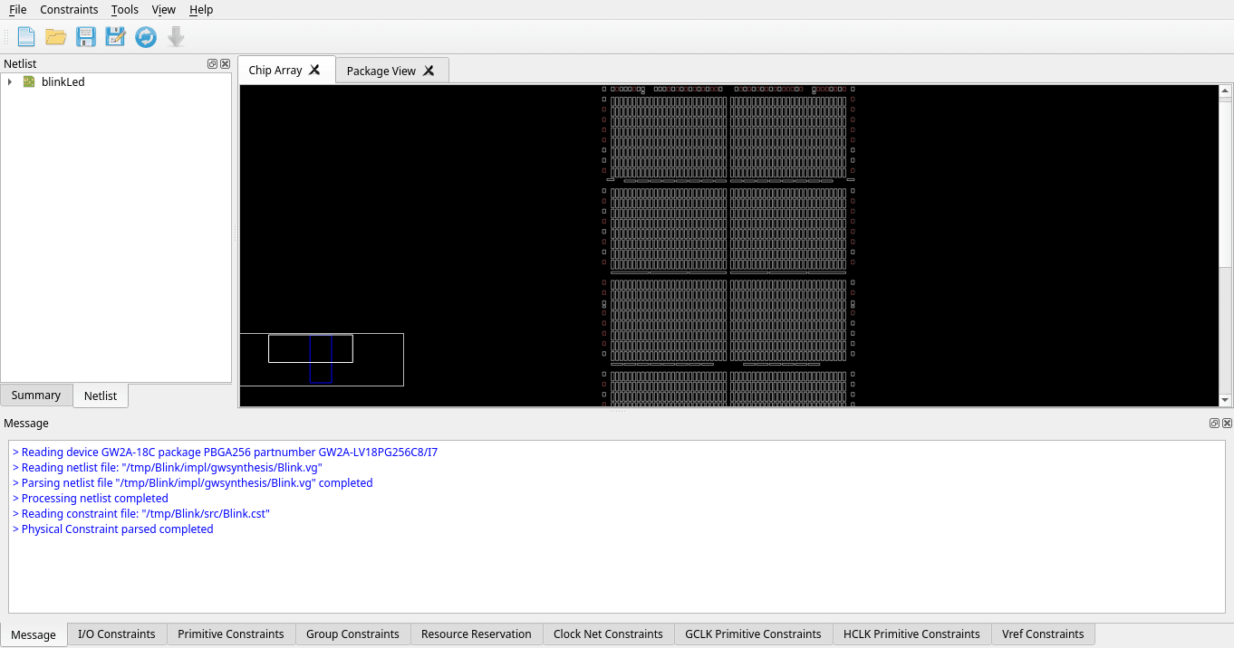
FloorPlanner opens showing the chip array with the netlist loaded.
Switch to the I/O Constraints tab and assign led and clock to the actual pins on your board, then save. On my Tang Primer 20K Dock that is N16 for led and H11 for clock.
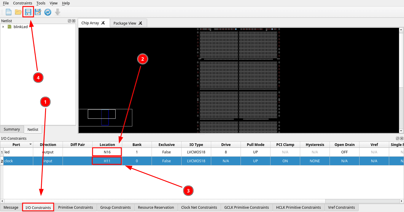
The led and clock pins are different for every board. Here is a table with pin mappings for multiple Sipeed FPGA boards.
| Name | Chip | LED Pin | Clock Pin |
|---|---|---|---|
| Tang Nano | GW1N-LV1QN48C6/I5 | 16 | 35 |
| Tang Nano 1K | GW1NZ-LV1QN48C6/I5 | 9 | 47 |
| Tang Nano 4K | GW1NSR-LV4CQN48PC6/I5 | 10 | 45 |
| Tang Nano 9K | GW1NR-LV9QN88PC6/I5 | 10 | 52 |
| Tang Nano 20K | GW2AR-LV18QN88C8/I7 | 15 | 4 |
| Tang Primer 20K Dock | GW2A-LV18PG256C8/I7 | N16 | H11 |
| Tang Primer 20K Lite | GW2A-LV18PG256C8/I7 | L14 | H11 |
| Tang Primer 25K Dock | GW5A-LV25MG121NC1/I0 | L6 | E2 |
| Tang Mega 60K Dock | GW5AT-LV60PG484AC1/I0 | P19 | V22 |
| Tang Mega 138K Pro Dock | GW5AST-LV138FPG676AC1/I0 | J14 | P16 |
The pin mappings can also depend on the exact board version, so check the documentation or schematic for your board if the LED does not blink.
Place and route
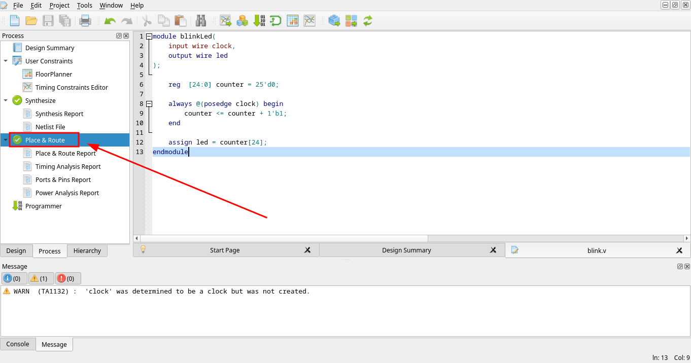
Back in the main window, double click Place & Route to run it.
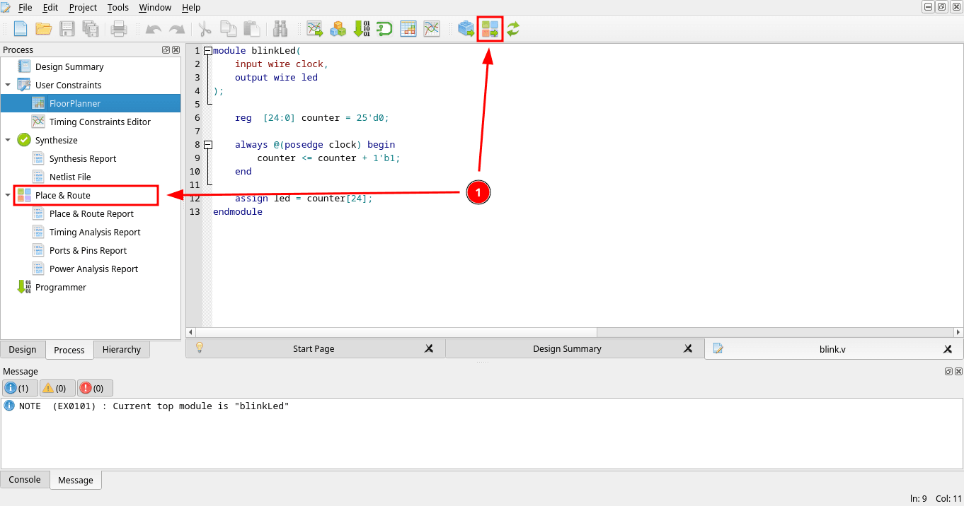
It finishes with a warning that clock was not recognized as a dedicated clock net. This worked fine for this small LED example, but for larger projects you should configure the clock properly and check the timing report.
Programming
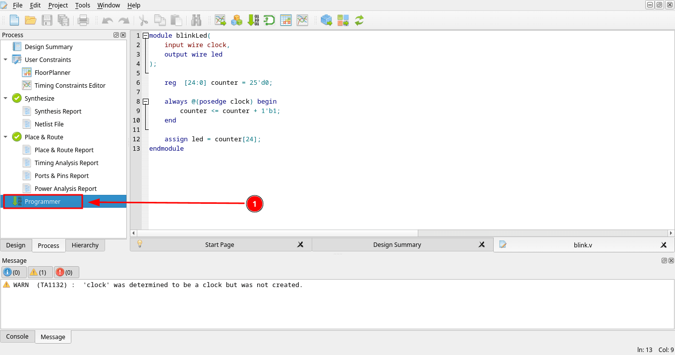
Everything is built, so open the Programmer tool to program the board.
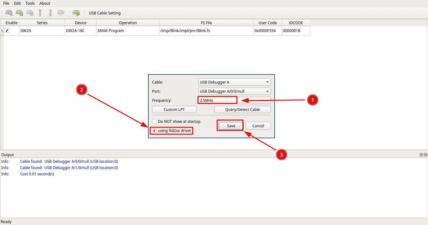
The USB Cable Setting window should pop up.
Make sure the frequency is set to 2.5 MHz. Other frequencies sometimes make programming fail on my setup.
Then enable the ftd2xx driver and click Save.
The exact cable settings can be different depending on your Sipeed board and programmer.
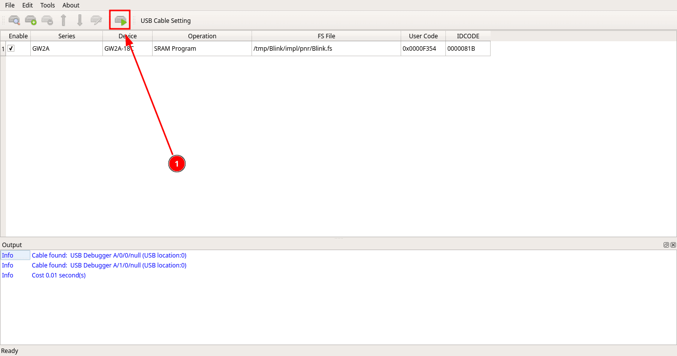
With SRAM Program selected as the operation, click the green Program/Download button.
Once it reaches 100%, the LED should already be blinking on the board. This is the fastest way to test, but it is only written to SRAM, so it will not survive a power cycle.
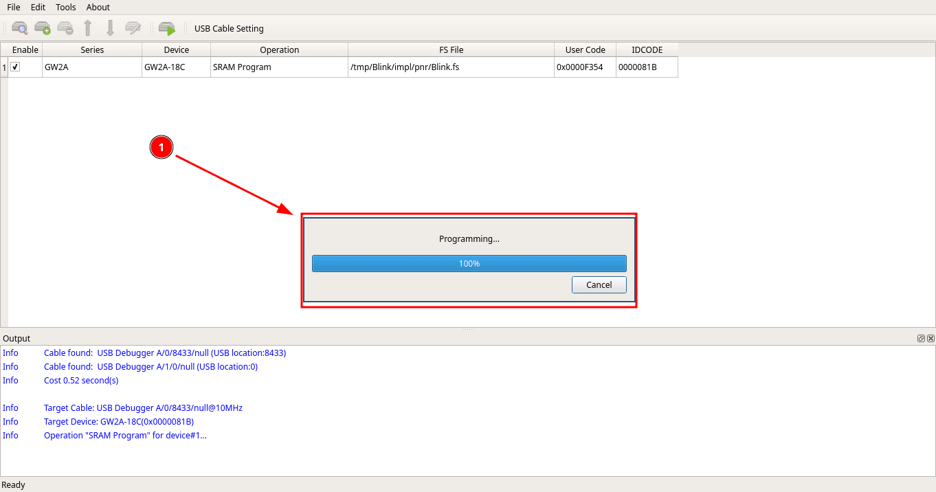
If programming fails, double check that you have the same settings as I do. Also, if you are following along with the Tang Primer 20K Dock, switch 1 needs to be in the down position so the core board is enabled.
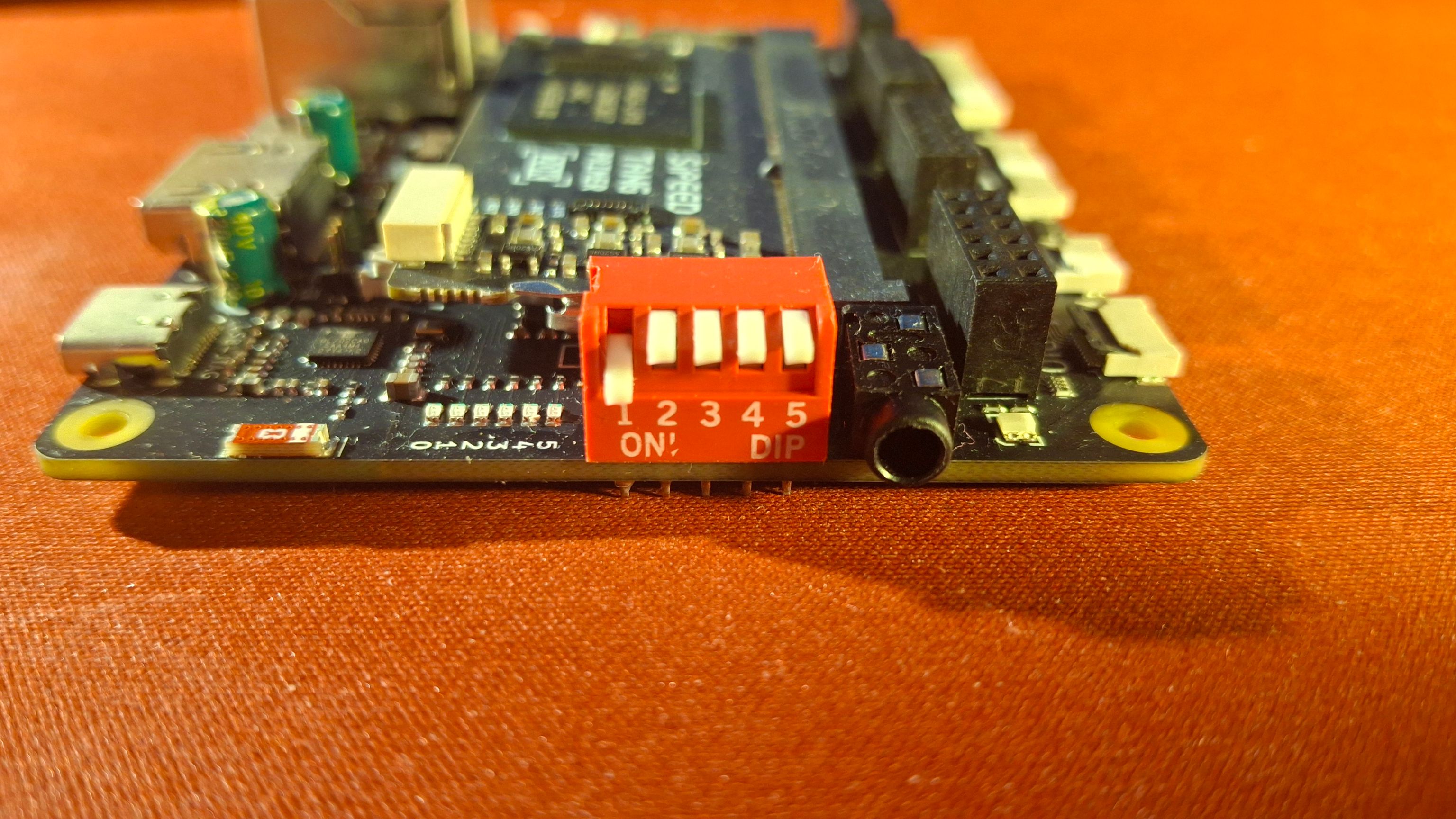
If you did everything correctly, the LED should start blinking.
Flashing to external memory
Even after trying for a long time, uploading to flash through Gowin Programmer never worked for me.
Fortunately, this can be done successfully and very easily with openFPGALoader.
The exact board name depends on your Sipeed board. The command below is for the Tang Primer 20K:
openFPGALoader -b tangprimer20k -f /tmp/Blink/impl/pnr/Blink.fsReplace tangprimer20k with the correct board name supported by openFPGALoader, and replace the file path with the path to the .fs file generated for your project.