Gowin IDE Tutorial: Debug FPGA Designs with the Gowin Analyzer Oscilloscope (GAO)
Learn how to use Gowin IDE's built-in GAO (Gowin Analyzer Oscilloscope) logic analyzer to capture and inspect internal FPGA signals directly on the FPGA without having to use an external oscilloscope.
![Captured waveform in the GAO Analyzer Oscilloscope showing counter[7:0] and trig, with the trigger marker aligned to trig's rising edge](/_ipx/w_1024&f_webp&q_80/images/GowinIdeGAO/oscilloscopeEdgeTrigger.png)
Preview of the Gowin Analyzer Oscilloscope
GAO is an embedded logic analyzer core that Gowin IDE stitches into your design. It samples the internal signals you choose, on the same clock as your design, and streams the captured samples back over the same USB cable used for programming. No external logic analyzer or extra pins are needed.
In this tutorial I will show you how to create a GAO configuration, pick a trigger condition, capture some internal signals, and view the resulting waveform right inside Gowin IDE.
The only prerequisite is knowing how to create a new Gowin project and a Verilog source file. These steps were covered in the first tutorial.
The example design
For this tutorial I am using a tiny standalone project called GaoExample, targeting the same GW2A-LV18PG256C8/I7 device as before. The only source file is top.v, containing a free running 8 bit counter:
module top(
    input clk,
    output reg [7:0] counter
);

    always @(posedge clk) begin
        counter <= counter + 1;
    end
endmodule
This is deliberately simple: counter just keeps incrementing on every rising edge of clk. It gives us a signal with a completely predictable pattern, which makes it easy to confirm that GAO is actually capturing what we expect.
Constraints file
The only constraint needed is for the clock pin.
IO_LOC "clk" H11;
IO_PORT "clk" IO_TYPE=LVCMOS33 PULL_MODE=NONE BANK_VCCIO=3.3;
Creating a GAO Config File
With the project synthesized at least once, click the New File icon and select GAO Config File from the list, then click OK.
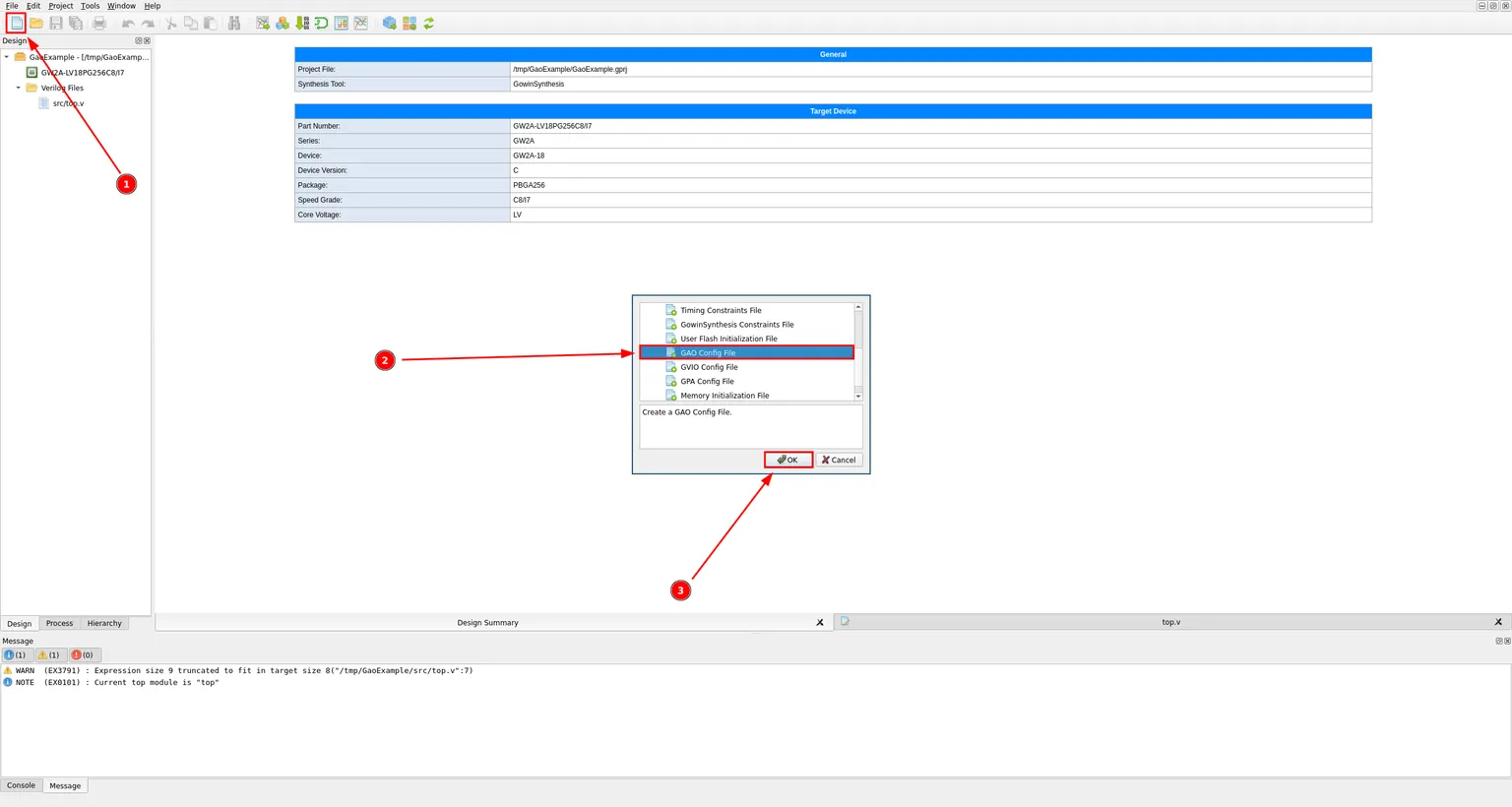
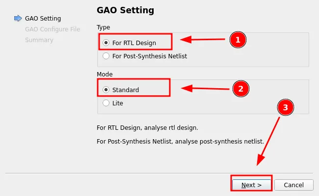
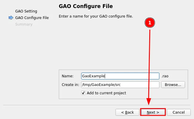
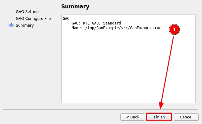
The GAO Setting wizard opens. Leave the type as For RTL Design, since we are analyzing the RTL design directly rather than a post-synthesis netlist, and leave the mode as Standard. Click Next. Give the configuration file a name. I called mine GaoExample. Gowin IDE will save it with a .rao extension inside the project’s src folder. Click Next. The last step summarizes the settings. Check it and click Finish.
The GAO editor
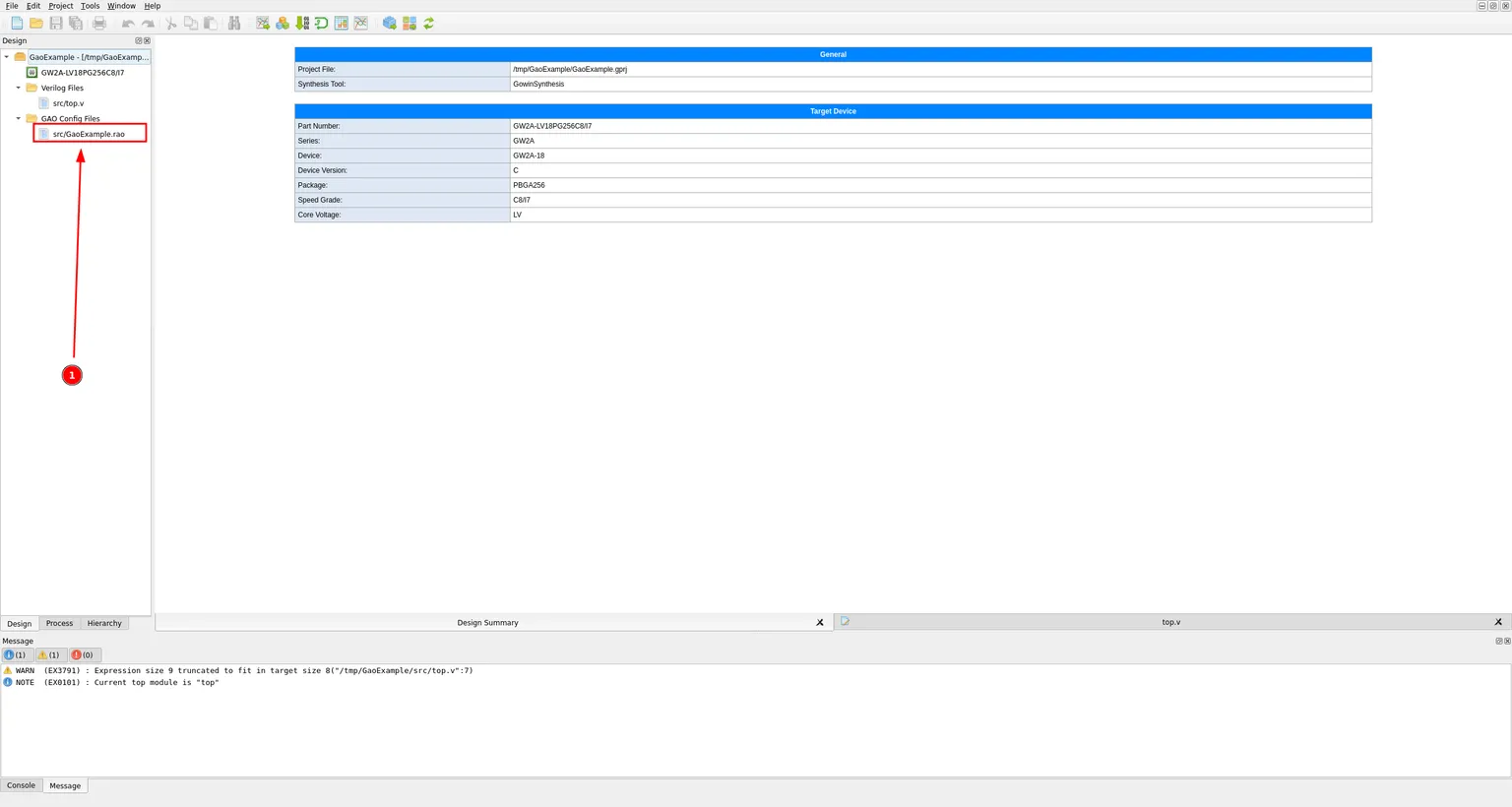
The new GaoExample.rao file now shows up in the project tree, under a new GAO Config Files group. Double click it to open the GAO editor.
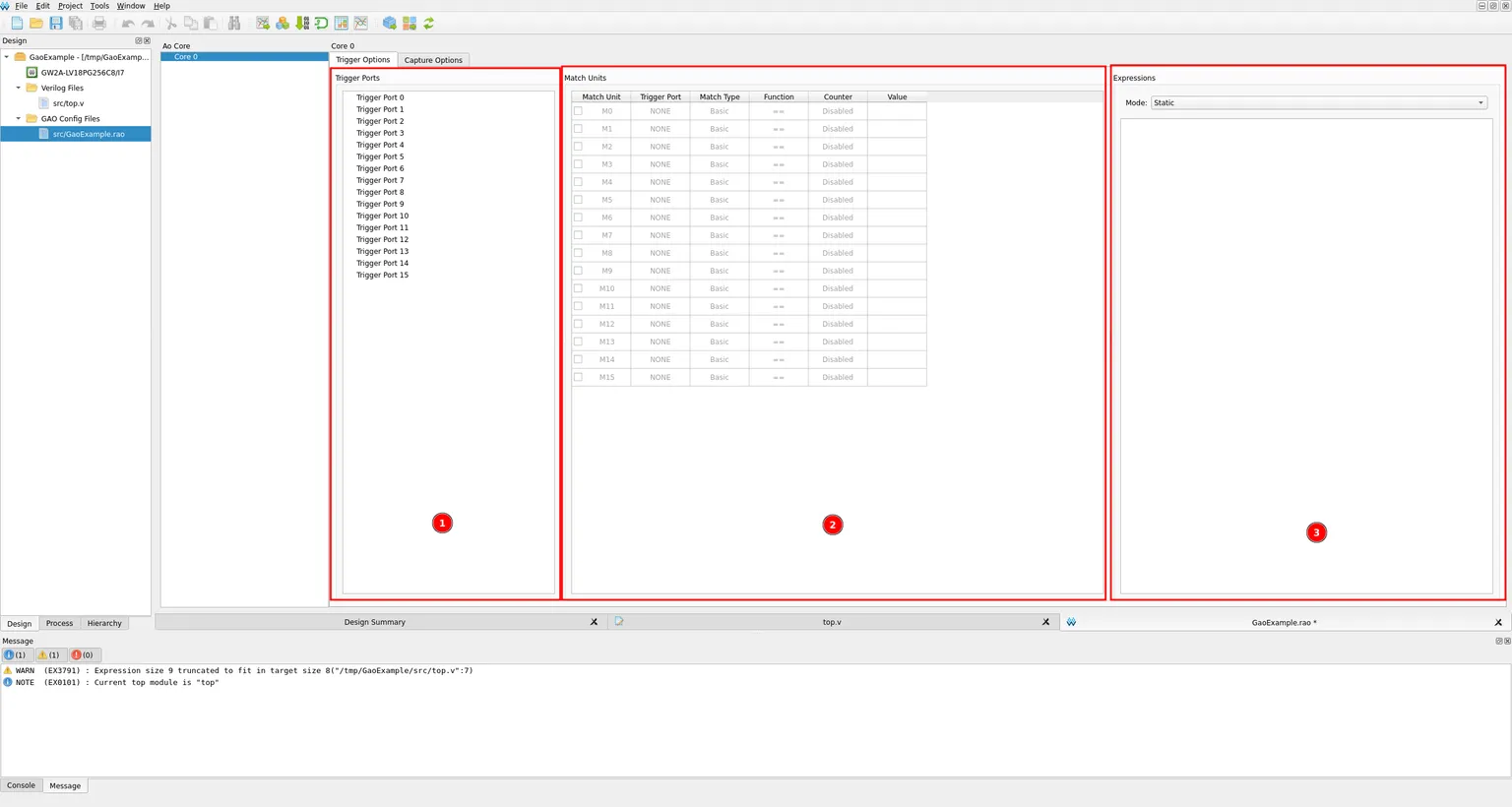
The GAO editor is organized per Core, and each core has two tabs. The Trigger Options tab has three panels: Trigger Ports on the left, where you pick which signals can be used to trigger a capture; Match Units in the middle, where you define the actual conditions to compare those signals against; and Expressions on the right, where you combine match units into the final trigger condition.
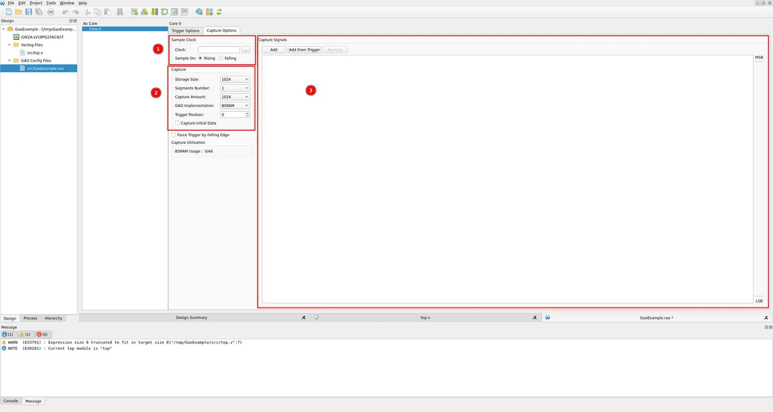
The Capture Options tab configures how sampling itself happens: the Sample Clock used to capture data, the Capture settings such as storage depth and trigger position, and the Capture Signals list of everything you actually want recorded in the waveform.
Setting up a trigger port
Selecting Trigger Port 0 reveals its empty signal list on the right.
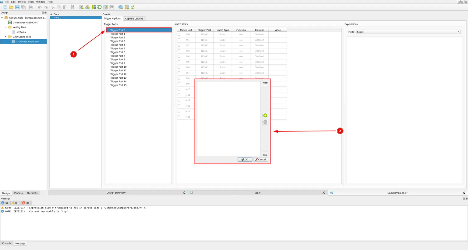
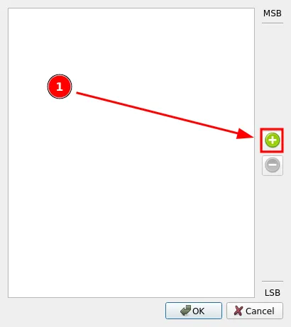
Click the green plus button to add a signal to this port.
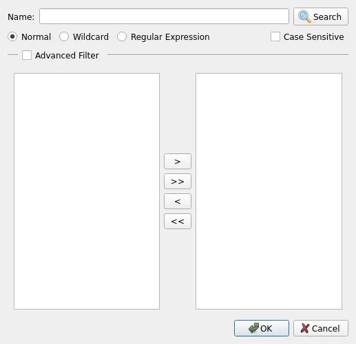
This opens a signal browser, empty until you hit Search. Leaving the Name field blank and clicking Search lists every available signal, which is handy on small projects like this one. On a bigger design, typing a name first narrows that list down.
Select counter[7:0] from the column on the left, and move it to the right pane with the > button.
![Signal browser filtering to counter[7:0] and clk, then moving counter[7:0] into the selected pane with the greater-than button](/_ipx/w_1536&f_webp&q_80/images/GowinIdeGAO/pinWindowAssignCounter.png)
Back in the trigger port panel, counter[7:0] is now listed. Click OK to save it to the port.
![Trigger port signal panel now containing counter[7:0] before clicking OK to save](/_ipx/w_1536&f_webp&q_80/images/GowinIdeGAO/saveTriggerPort.png)
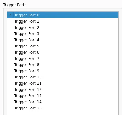
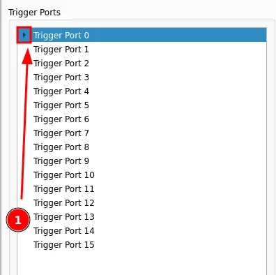
Click the small arrow next to Trigger Port 0 any time to expand or collapse it and check which signal is assigned.
![Trigger Port 0 expanded to reveal counter[7:0] as its assigned signal](/_ipx/w_1536&f_webp&q_80/images/GowinIdeGAO/triggerPortDetails.png)
Configuring a Match Unit
Trigger ports on their own do not trigger anything. A Match Unit compares a trigger port against a value, and it is the match units that expressions are built from. Each match unit is configured through a Match Type and a Function dropdown, and there are six match types to pick from, each supporting a different set of comparison functions and bit values:
| Type | Bit Values | Matching Function | Description |
|---|---|---|---|
Basic | 0, 1, X | ==, != | General signal comparison; the cheapest one on resources. |
Basic w/edges | 0, 1, X, R, F, B, N | ==, !=, jump detection | Adds jump (edge) detection to control on a signal transition. |
Extended | 0, 1, X | ==, !=, >, >=, <, <= | Ordered comparisons against an address or data value. |
Extended w/edges | 0, 1, X, R, F, B, N | ==, !=, >, >=, <, <=, jump detection | Ordered comparisons plus jump detection. |
Range | 0, 1, X | ==, !=, >, >=, <, <=, in/out of range | Whether an address or data value falls inside or outside a range. |
Range w/edges | 0, 1, X, R, F, B, N | ==, !=, >, >=, <, <=, in/out of range, jump detection | Range detection plus jump detection. |
0means low level.1means high level.Xmeans either level.Rindicates a rising edge,0to1.Findicates a falling edge,1to0.Bindicates either a rising or falling edge.Nmeans no level transition.
This tutorial only needs two of these: Basic, for a plain equality check, and later Basic w/edges, to catch a signal’s rising edge. Check the box next to M0 to enable it, then double-click on its row to open the Match Unit 0 dialog.
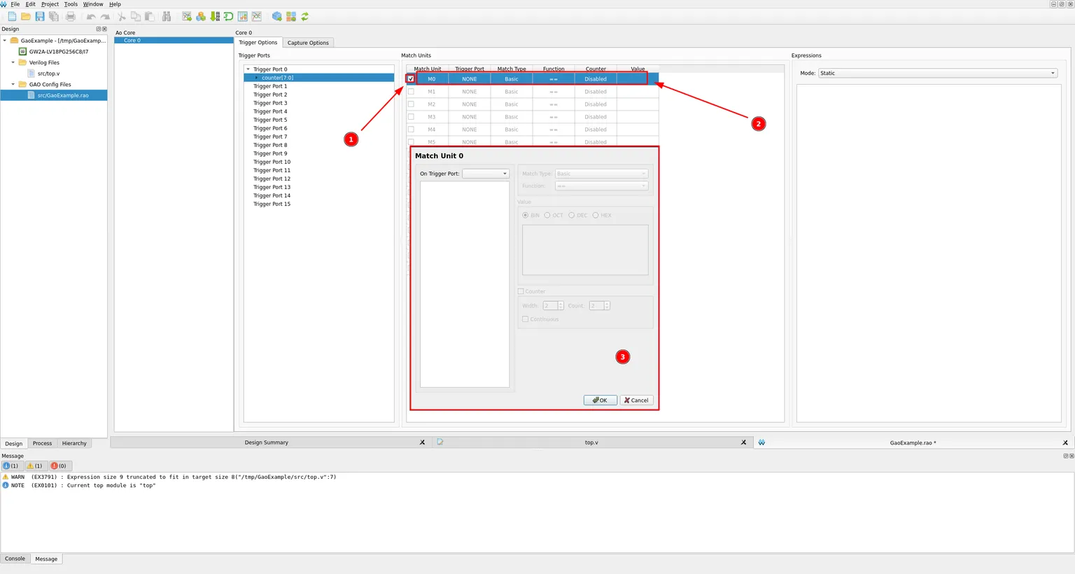
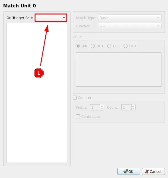
The dialog opens with nothing selected yet. Pick Trigger Port 0 from the On Trigger Port dropdown.
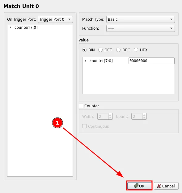
With Trigger Port 0 selected, counter[7:0] appears on the left. Leave the function as == and enter 00000000 in binary as the value to match, so the unit fires the instant the counter wraps back to zero. Click OK.
Building the trigger expression
Match units still need to be combined into an expression before they can actually trigger a capture. In the Expressions panel, leave Mode as Static and click into the empty expression box.
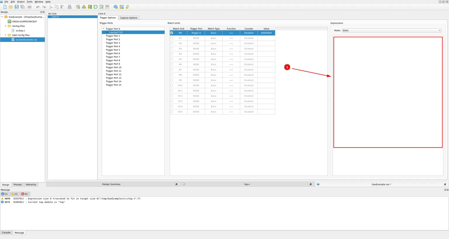
A small calculator style keypad opens, with a button for every match unit plus the logic operators needed to combine them.
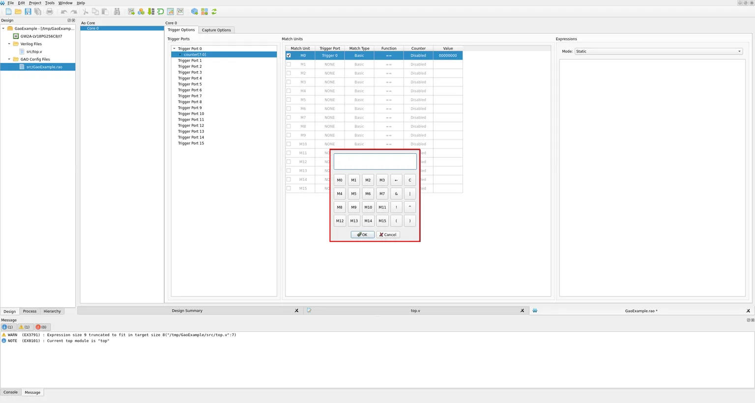
Since we only need M0, click its button and then OK.
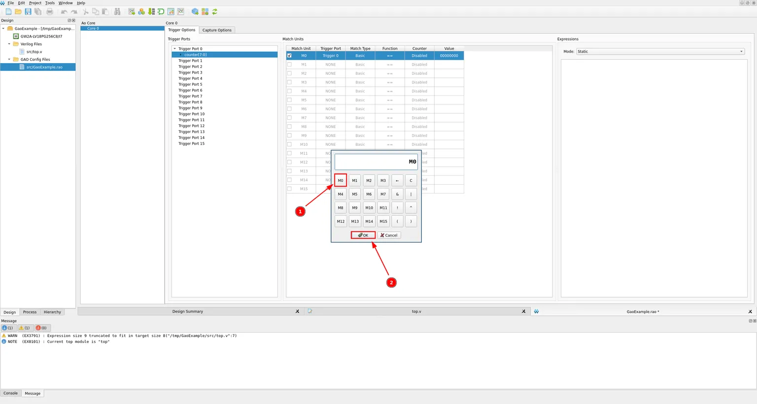
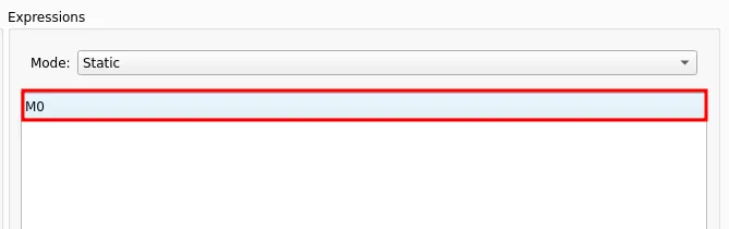
The expression M0 is now listed, meaning GAO will trigger exactly when match unit 0 evaluates true, that is, the moment counter[7:0] equals zero.
Capture settings
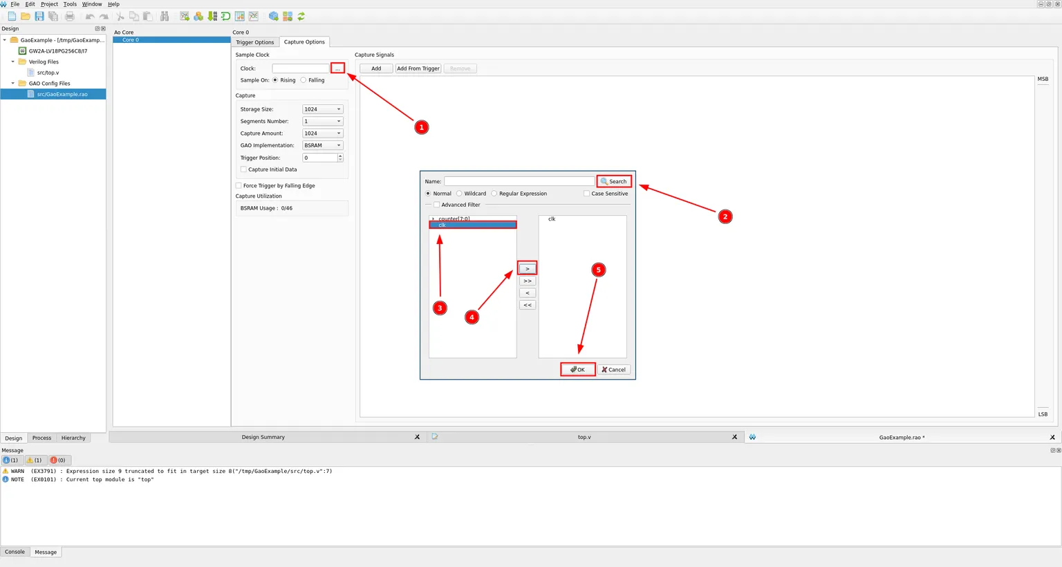
Switch to the Capture Options tab. Click the ... button next to Clock, search for and select clk, and click OK. This is the clock GAO uses to sample every signal.
Click Add in Capture Signals, search for counter, select counter[7:0], move it to the right pane, and click OK. This is what actually ends up in the waveform, separately from whatever you used for the trigger.
![Capture Signals list adding counter[7:0] through the signal browser](/_ipx/w_1536&f_webp&q_80/images/GowinIdeGAO/setupCaptureSignals.png)
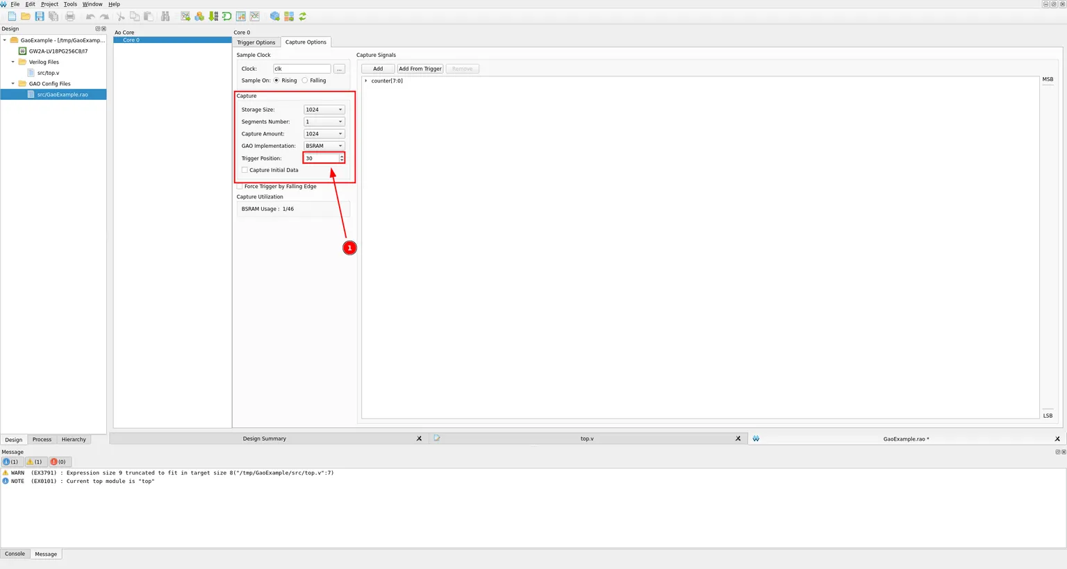
The capture buffer holds 1024 samples by default. Setting Trigger Position to 30 tells GAO to keep 30 samples from before the trigger event and the rest from after it, which is useful to see what led up to the trigger, not just what followed it.
Saving and building
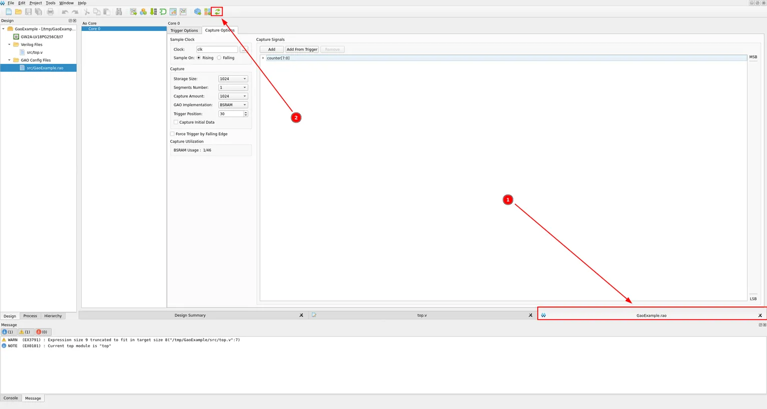
Save the .rao file. Notice the tab title carries an asterisk while there are unsaved changes, and loses it once saved.


Click the Rerun All icon in the toolbar to synthesize and place & route the design again. This time, the GAO core gets stitched into the bitstream alongside your design.
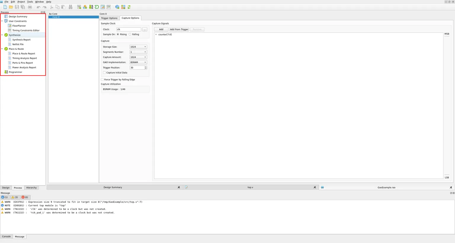
Once both Synthesize and Place & Route finish with green checkmarks, the build is ready to program.
Programming the GAO bitstream
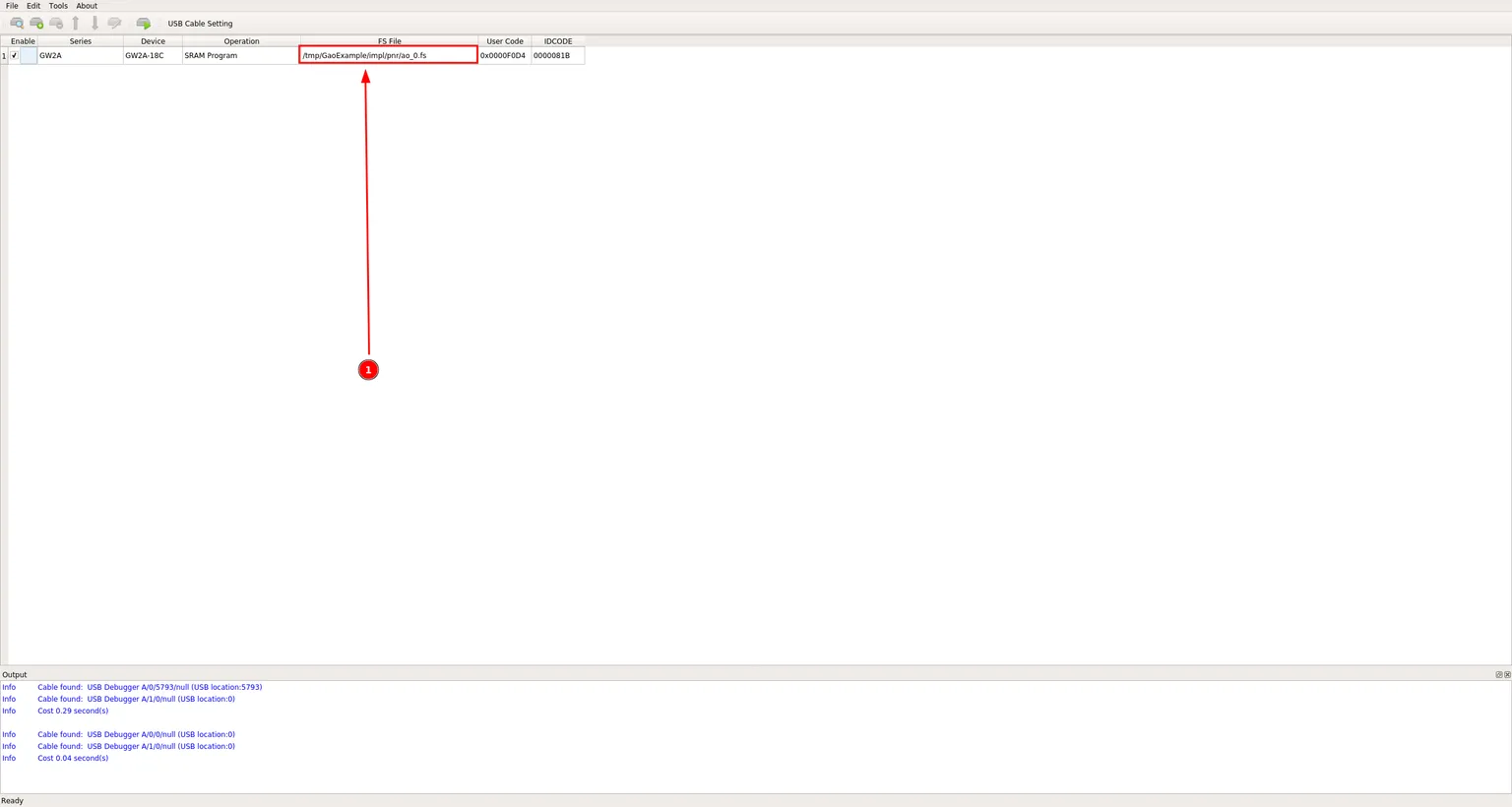
Program the board as usual, but pay close attention to the FS File. Building with a GAO core produces its own bitstream, ao_0.fs, which includes the analyzer logic alongside your design.
If you had already built the project once before creating the GAO configuration, impl/pnr will still contain the plain bitstream from that earlier build (GaoExample.fs in this case), since building with GAO does not delete it, it just adds ao_0.fs next to it.
That old file still programs and runs fine, it just has no GAO core in it, so double check FS File points at ao_0.fs and not a stale file left over from before you added GAO.
Running a capture
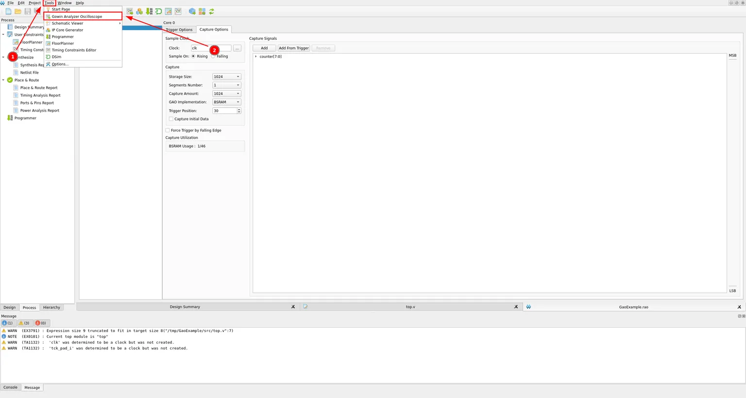
Open the Gowin Analyzer Oscilloscope tool from the Tools menu.
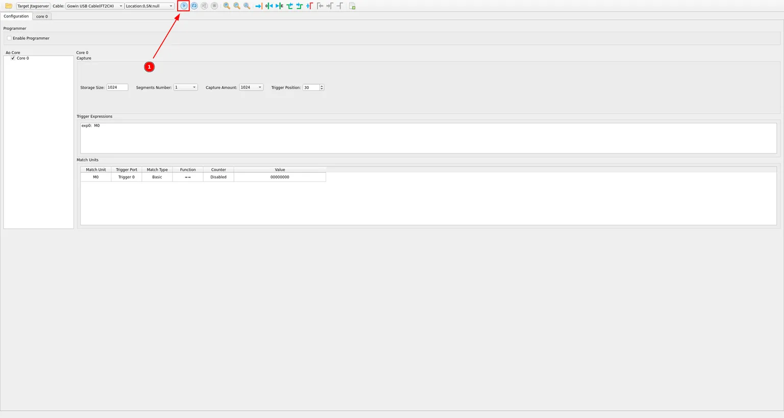
The Configuration tab also shows the trigger and match unit settings from the project file, so you can double check exp0: M0 is set up correctly before running. Click the Run button to arm the trigger and start waiting for a match.
As soon as counter[7:0] reaches zero, the trigger fires and GAO streams the capture back. The core 0 tab shows counter[7:0] as a bus, printed in hex, with the orange marker at sample 30 showing exactly where the trigger landed, right where the value rolls over to 00.
![Captured waveform of counter[7:0] as a hex bus, with the trigger marker at sample 30 where the value rolls over to 00](/_ipx/w_1536&f_webp&q_80/images/GowinIdeGAO/gaoOscilloscope.png)
Expand counter[7:0] to see every individual bit as its own binary waveform. You can clearly see each bit toggling at half the rate of the one below it, exactly what you would expect from a binary counter.
![counter[7:0] expanded into its individual bits, each shown as a separate binary waveform](/_ipx/w_1536&f_webp&q_80/images/GowinIdeGAO/gaoOscilloscopeExpanded.png)
Zooming out a little confirms the counter keeps incrementing cleanly, one step per clock cycle, well beyond the trigger point.
![Zoomed out waveform view confirming counter[7:0] keeps incrementing by one every clock cycle](/_ipx/w_1536&f_webp&q_80/images/GowinIdeGAO/gaoOneCycle.png)
And that’s it. You now have a working internal logic analyzer for any Gowin FPGA design, without needing a single extra pin.
Advanced triggers
So far every trigger has fired on a static value, counter[7:0] == 0. GAO can also trigger on a signal’s edge rather than its level, which is a better fit for a one-shot event like a counter overflow. To try it, add a trig register to top.v that pulses for exactly one cycle every time counter wraps around:
module top(
    input clk,
    output reg [7:0] counter
);

    reg trig;

    always @(posedge clk) begin
        counter <= counter + 1;
        trig <= &counter;
    end
endmodule
Expand the box below if you want the full story of why the obvious approach doesn’t quite work.
Code explained: Why not just if (counter == 0)?
First idea on how to write the code might be:
module top(
    input clk,
    output reg [7:0] counter
);

    reg trig;

    always @(posedge clk) begin
        counter <= counter + 1;

        if (counter == 0)
            trig <= 1;
        else
            trig <= 0;
    end
endmodule
This looks reasonable, but it is wrong. Every signal on the right-hand side of a non-blocking assignment (<=) is read using its value from before this clock edge, and counter is no exception: the comparison counter == 0 still sees the old value, one cycle behind the counter <= counter + 1 that is scheduled to happen at the same edge. So by the time trig actually goes high, counter has already moved on to 1. The capture below still uses the original counter[7:0] == 0 trigger from earlier in this tutorial, but with trig also being recorded: the capture still lands right where counter hits zero, yet trig only rises one sample later.
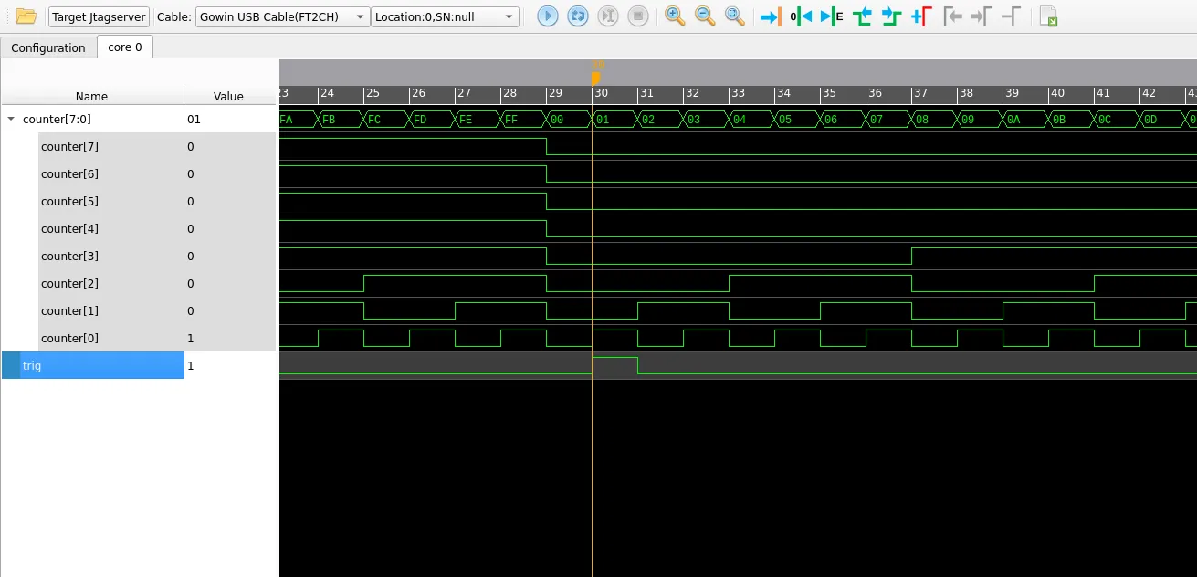
Trigger is on the value when counter is 1, not 0
Comparing against the last value before the wrap fixes the timing:
always @(posedge clk) begin
    counter <= counter + 1;

    if (counter == 8'hFF)
        trig <= 1;
    else
        trig <= 0;
end
This works, but 8'hFF has to be updated by hand every time counter changes width. Comparing against the next value instead seems like it should avoid that problem entirely:
if ((counter + 1) == 0)This does not work: counter + 1 and 0 are both evaluated at whatever width Verilog decides for the expression, which does not necessarily match counter’s width, so the comparison never wraps the way you would expect. Sizing every literal explicitly fixes it:
if ((counter + 8'd1) == 8'd0)but that still needs to be edited by hand whenever the register’s width changes. The width-independent way to detect “all bits are 1” is the reduction-AND operator, &counter: it collapses every bit of counter down to a single bit that is 1 only when they are all 1. Since that is exactly the state right before the counter wraps to zero, it is exactly the condition we want:
8-bit:  11111111            -> &counter = 1
16-bit: 1111111111111111    -> &counter = 1
32-bit: all ones            -> &counter = 1
always @(posedge clk) begin
counter <= counter + 1;
if (&counter)
trig <= 1;
else
trig <= 0;
endAnd since trig is just being assigned the result of a boolean expression either way, the if can be dropped entirely:
module top(
    input clk,
    output reg [7:0] counter
);

    reg trig;

    always @(posedge clk) begin
        counter <= counter + 1;
        trig <= &counter;
    end
endmodule
This version keeps working no matter how wide counter ends up being, without touching anything besides its declaration.
Triggering on an edge
With trig added to the design, rebuild it (Rerun All, as before) and reopen GaoExample.rao. The old Trigger Port 0 still points at counter[7:0]; remove it by selecting the signal in the port’s list and clicking the red minus button.
![Trigger Port 0 with counter[7:0] selected and the red minus button highlighted to remove it](/_ipx/w_1536&f_webp&q_80/images/GowinIdeGAO/removeOldTriggerPort.png)
Add trig to the now-empty port the same way as before: search for it, select it, and move it across.
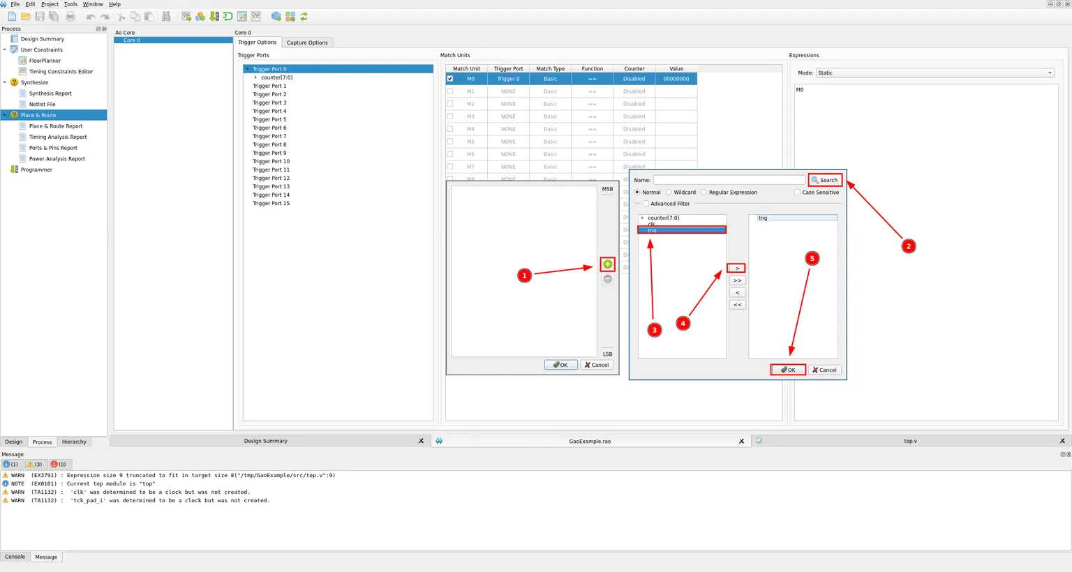
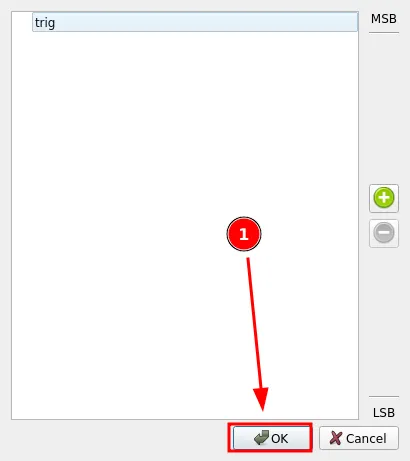
Click OK to save trig as the port’s only signal.
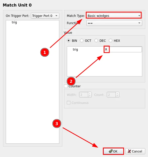
Open Match Unit 0 again. This time change Match Type to Basic w/edges, and instead of a static binary value, type R into trig’s value field to match its rising edge specifically, rather than just any moment it happens to be high.
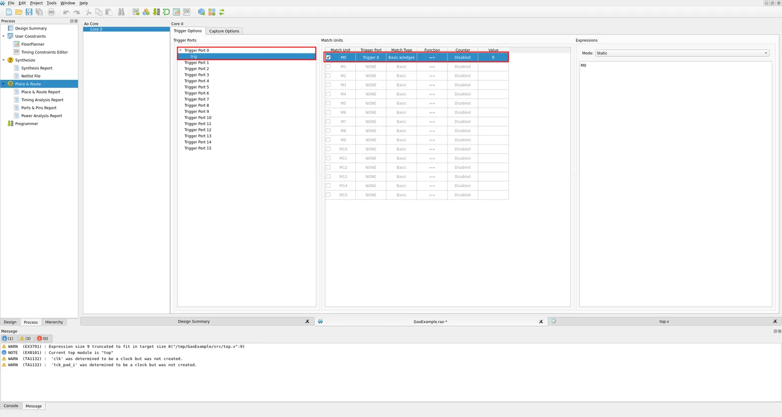
The Trigger Options tab now reflects all of this: Trigger Port 0 carries trig, and M0 matches its rising edge, still combined into the same M0 expression as before.
Switch to Capture Options and click Add again to also record trig in the waveform alongside counter[7:0], using the same search-and-select process as before. trig now shows up in the capture signal list too.
![Capture Signals list with counter[7:0] already present and the Add button highlighted to add another signal](/_ipx/w_1536&f_webp&q_80/images/GowinIdeGAO/addCaptureSignalTrig.png)
![Capture Signals list now containing both counter[7:0] and trig](/_ipx/w_1536&f_webp&q_80/images/GowinIdeGAO/addedTrigCaptureSignals.png)
Save, rebuild, reprogram and run the capture again. This time the trigger fires exactly on trig’s rising edge, right as counter wraps around.
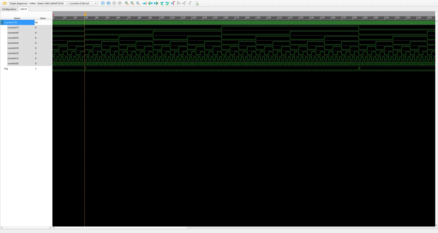
That’s working edge triggering. Instead of waiting for a signal to have a specific value, GAO can catch the exact instant it changes, which is often more powerful when looking for something.